


6
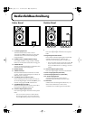
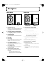
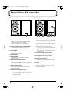
Panel Description
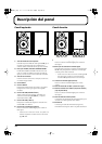
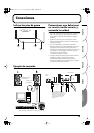
Left Channel
fig.2
1.
L Channel Input Jack
Connect this to L Channel Output Jack
14
on the right-
side unit. For the connection, use the included speaker
cable.
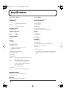
2.
POWER Switch, POWER/STANDBY Indicator
The POWER/STANDBY Indicator lights up in red
during standby, and lights up in green when power is on.
3.
PHONES Jack
When you connect headphones to this jack, no sound
will be heard from the speakers.
4.
BASS Control Knob
5.
TREBLE Control Knob
These adjust the tones of the bass and treble. Set to center
to make the tones flat.
6.
VOLUME Knob (DIGITAL/LINE 1)
This adjusts the volume of devices connected to digital
input connectors
8
,
9
,
11
, and LINE 1 Input Jack
12
.
7.
VOLUME Knob (LINE 2)
This adjusts the volume of the device connected to LINE
2 Input Jacks
13
.
8.
Digital Input Connector (Optical)
This is the digital input connector for optic-fiber cable.
* When you connect a cable to this connector, the sound of
devices connected to digital input connector
9
or
11
will
not be heard.
Right Channel
fig.3
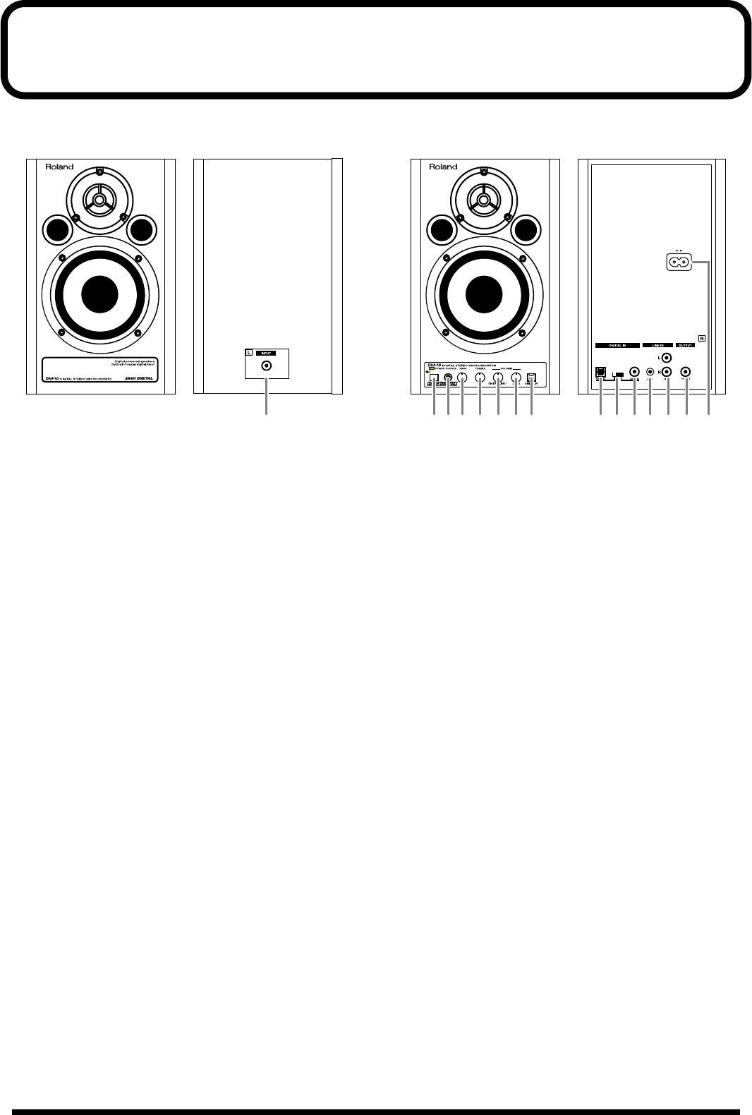
9.
Digital Input Connector (Optical)
This is the digital input connector for optic-fiber cable.
10.
Digital Input Select Switch
This switch selects digital input connector
9
or
11
on the
rear panel. Select the connector used for the input signal.
* When you connect a cable to digital input connector
8
on
the front panel, the sound of the device connected to
8
will be heard independently of this switch.
11.
Digital Input Connector (Coaxial)
This is the digital input connector for coaxial cable.
12.
LINE 1 Input Jack (stereo mini type)
13.
LINE 2 Input Jacks (L, R) (RCA pin type)
14.
L Channel Output Jack
Connect this to L Channel Input Jack
1
on the left-side
unit.
15.
AC Inlet
Connect the included Power cord here (p. 17). Plug it
firmly in, so that the cable does not accidentally become
disconnected.
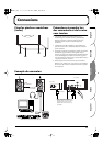
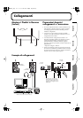
FROM RIGHT
1
234 5678 1213 14 15
9 10 11
DM-10_efgis 6ページ 2004年1月8日 木曜日 午後1時59分