


4 Address Map and Special Registers
This chapter explains how the four UARTs and special registers are addressed, as well as
the layout of those registers. This material will be of interest to programmers writing driver
software for the QSC-100.
4.1 Base Address and Interrupt Level (IRQ)
The base address and IRQ used by the QSC-100 are determined by the BIOS or operating
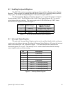
system. Each serial port uses 8 consecutive I/O locations. The four ports reside in a single block
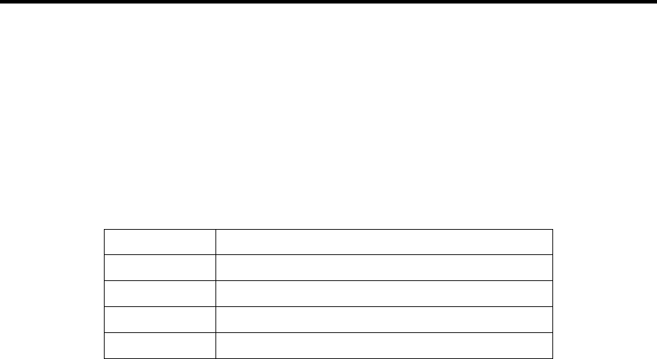
of I/O space in eight byte increments, for a total of 32 contiguous bytes, as shown in Figure 5.
Base Address + 24 to Base Address + 31Serial 4
Base Address + 16 to Base Address + 23Serial 3
Base Address + 8 to Base Address + 15Serial 2
Base Address + 0 to Base Address + 7Serial 1
I/O Address RangePort
Figure 6 --- Port Address Map
All four serial ports share the same IRQ. The QSC-100 signals a hardware interrupt
when any port requires service. The interrupt signal is maintained until no port requires service.
Interrupts are level-sensitive on the PCI bus.
The base address and IRQ are automatically detected by the device drivers Quatech
supplies for various operating systems. For cases where no device driver is available, such as for
operation under DOS, Quatech supplies the "QTPCI" DOS software utility for manually
determining the resources used. See page 0 for details.
Quatech QSC-100 User's Manual 9