


9
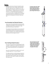
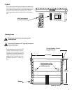
Fly Grid
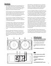
The mounting plate and link bar are located on the bottom side
of the frame assembly. Use this link for attaching the rear of the
first enclosure. The frame allows for up or down angle options
for use with either stacking or suspending. The 4° “normal”
locations on the link system will yield a net 0° vertical inclina-
tion.
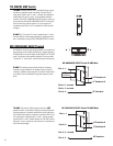
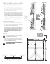
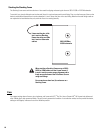
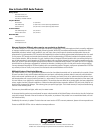
Stacking Frame
Do not stack more than four (4) enclosures on a
Stacking Frame.
Use only 5/16” diameter x 1.25” long ball-lock pins on
front receiver tubes.
The Stacking Frame interfaces with QSC’s
215PCM or 215SB subwoofer in either a
stacked or flown configuration. The stack-
ing bumpers on the frame may need to be
moved to the opposite side of the frame
member for use. The small frame is con-
structed using standard “L” track for rig-
ging.
Use 4° link location for
0° vertical inclination
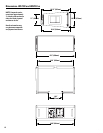
5/16 inch diameter, 1.25 inch
long ball-lock pins
Stacking bumpers align
with stand sockets of QSC
215PCM subwoofer
Bumpers
Standard L-track
25.7” (653mm)
19.5”
(495mm)