


7
Rigging
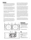
WideLine enclosures use a three-point suspension system.
The system consists of front, left/right, captive articulated
joints and a single rear link bar. Articulation is in 2° incre-
ments using the first location on the link bar. With the use of
the second location, 1° degree increments can be obtained
starting at 3°. The total available angular increments are: 0,
2, 3, 4, 5, 6, 7, 8, 9, and 10°. All pieces and locking pins
remain with the enclosures. No ancillary items are needed to
suspend the enclosures from the WideLine array frame. All
ball-lock pins are equipped with a lanyard to help prevent
loss.
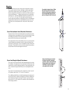
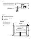
Front Articulated Joint (Knuckle) Hardware
Expose the end of the articulated joint by locating the joint’s
retaining screw protruding from the front of the receiver tube
and sliding it upward. The front captive joint will slide
upward from the enclosure’s receiver tube.
The exposed end of the articulated joint can now be inserted
into the adjacent enclosure’s receiver tube and locked into
position by a locking pin. This is repeated for each side of the
enclosure. Then the rear link bar can be rotated into position
and pinned at the chosen degree increment.
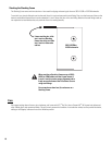
Rear Link (Angle Adjust) Hardware
The rear link is stored with the link folded between the sides
of the block. To expose the link, remove the ball-lock pin and
rotate the link into the desired position. Once positioned, the
link is secured using the ball-lock pin of the adjacent enclo-
sure.
The rear link is marked with a thin, white line at the “normal”
(0°) position and with a “+3” at the +3° position.
The additional ball-lock pin hole (located approximately mid-
way on the link) is used for storing the link when folded into
the enclosure’s block for storage. The link may be pinned in
place at the 0° or 8° location on the block when rotated into
the storage position.
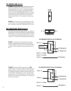
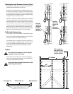
Front Articulated Joint- Slide
the joint out of the receiver
tube by sliding the retaining
screw upward, then lock in
place using the ball-lock pin.
Rear Link-Remove the ball
lock pin from the storage
position, then rotate the link
downward to the adjacent
enclosure. Lock in place
using the ball-lock pin.