


18
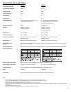
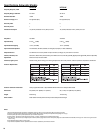
Specifications, Subwoofer Models
HPR151W HPR181W
Frequency Response, ±6dB 47-110 Hz 42-110 Hz
Frequency Range, -10dB limit 43-140 Hz 39-140 Hz
Maximum Peak SPL 133dB 134dB
Nominal coverage, H x V Not applicable (N/A) Not applicable (N/A)
Directivity Index 00
Directivity Factor 11
Transducer Description 15” (381mm) transducer with 3” (76mm) voice coil 18” (457mm) transducer with 4” (102mm) voice coil
Amp Power 700 Watts 700 Watts
Input Sensitivity 0.775 V
rms
(+0dBu) 0.775 V
rms
(+0dBu)
Input Headroom/Clipping 10 V
rms
(+22.2dBu) 10 V
rms
(+22.2dBu)
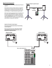
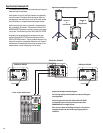
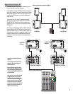
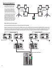
Input Connectors/Impedance Two XLR female, 22k Ohm, balanced, left and right (L+R) inputs (11k Ohms unbalanced)
Output Connectors Four XLR male: two wired in parallel with Input connector (full range), two post-100 Hz low-cut filters
Controls, Indicators, and Gain control, Phase switch (normal/reverse), Front LED on/off switch, Limit/Clip (red LED), Signal presence (green LED), AC Power (blue LED)
Adjustments AC Power switch, AC circuit breaker
Protection, Agency certs. Thermal limiting, On/Off muting, power limiting, DC protection, short circuit protection, ultrasonic protection, RF protection, UL/CE listed
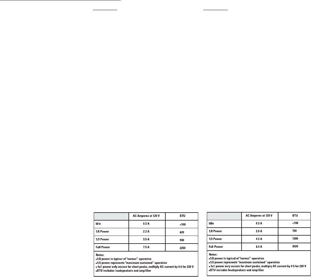
AC Power Requirements
AC Power Connector and Cordset Factory supplied IEC cordset: 6’ (2m) #18AWG 120V North American or European 230V cordset
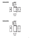
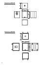
Dimensions 25” (635mm) x 22” (559mm) x 21” (525mm) 28” (711mm) x 24” (595mm) x 23” (582mm)
Weight 98 lb/44.5 kg 127 lb/57.6 kg
Finish and Grill Wear-resistant textured paint finish with powder-coated perforated steel grill
Notes:
1- Maximum Peak SPL: Calculated by adding the loudspeaker’s sensitivity (1W at 1m) to the peak power (dBw) of the amplifier provided.
2- Directivity Index (DI): Difference between on-axis SPL and average SPL (considering all axes) for the specified coverage range. DI= 10 log Q
3- Directivity Factor (Q): Directivity index expressed as a power ratio Q=10 exp DI/10
4- Amplifier Power: The maximum sustained power at less than 1% clipping, averaged over the intended frequency range,
5- Input Sensitivity: The sine-wave input voltage required to reach amplifier clipping, measured within the frequency range used to determine Maximum Peak SPL, with the gain on “normal” and no gain reduction
due to limiting.
6- Input Headroom/Clipping: Maximum input voltage.
7- Input Connector/Impedance: RF shunt capacitance should not reduce impedance by more than 30% at 20k Hz.