


13
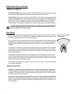
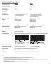
Application Example #3
This example shows a two-channel (stereo) setup utiliz-
ing two subwoofers and two top-boxes.
Audio signals for the Left and Right channels are supplied
by the mixer console. This signal source can be just about
any variable-output level audio source, such as DJ mix-
ers, professional CD players, or computer-based audio
signal sources.
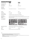
Audio output from the mixer is connected to the sub-
woofer input of each channel. Each subwoofer’s FULL
RANGE LINE OUT connector is used to connect to its
respective top-box. Turn ON the top-box’s 100 Hz LOW-
CUT FILTER.
Alternately, the top-boxes could be connected to the sub-
woofer’s 100 Hz LOW-CUT OUT and the top-box 100 Hz
LOW-CUT FILTER turned off. The only possible issue with
this method of connection is unexpected noises (turn-off
thumps) if the subwoofer is powered down before the
top-boxes. If connected as shown, power sequencing is
not an issue.
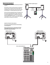
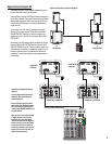
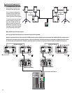
Application Example #3 physical diagram.
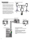
Application Example #3 hookup
diagram.
Use only high-quality balanced
cables for interconnecting the
audio equipment.
Ensure the top-boxes have their
100 Hz LOW-CUT FILTER switched
ON when connecting to the sub-
woofer’s FULL RANGE LINE OUT as
a signal source.
Also, be sure to use either the Left
or Right (marked L or R) on the
subwoofers. If the subwoofer’s
input is connected to the Right (R)
channel connector and the output
to the top-boxes is connected to
the Left (L) channel connector, no
signal will reach the top-box (no
sound from the top-box).
HPR152F or
HPR153F
HPR151W or HPR181W
HPR151W or HPR181W
Mixer or Other Audio Source
Channel 1
or
Left Channel
Channel 2
or
Right Channel
HPR152F or
HPR153F