


6
<PRB1289>
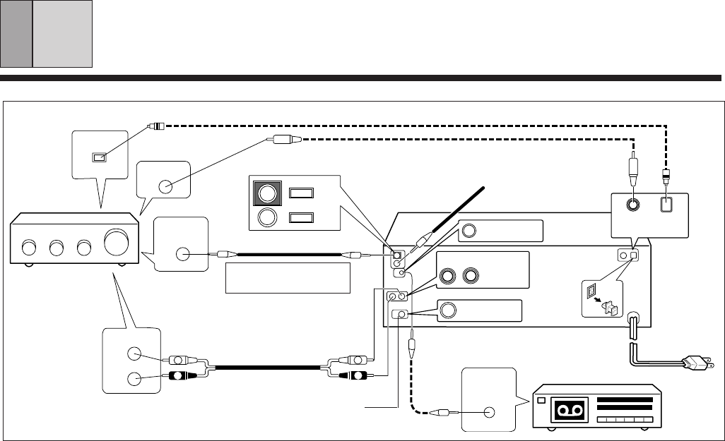
CONNECTIONS
A Making connections
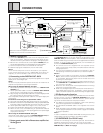
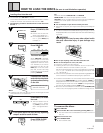
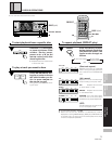
1 Connect the OUTPUT jacks of this unit to the input jacks (CD or
AUX) of the amplifier. Make sure that the white plugs are con-
nected to the left (L) jacks and the red plugs to the right (R) jacks.
÷ Be sure not to connect this unit to the amplifier’s PHONO jacks, as
sound will be distorted and normal playback will not be possible.
2 Connect the power cord to a household AC wall outlet.
÷ Make sure plugs are inserted fully into the wall outlet.
Note!!
Do not connect the power cord to an AC outlet on your amplifier.
If you connect the power cord to a "SWITCHED" AC outlet on an
amplifier, you will not be able to use this unit's memory function.
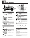
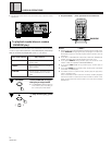
When a Pioneer stereo amplifier bearing the Î mark is used, connect
the CONTROL IN jack on the rear panel of the CD player to the
CONTROL OUT jack of the amplifier. This will enable the CD player
to be controlled using the remote control unit supplied with the stereo
amplifier. If you do not plan to use this feature, it is not necessary to
connect the CONTROL IN/OUT jacks.
÷ The remote control unit supplied with the amplifier can be
used to control Play, Stop, Pause, Track/Disc Search and Disc
Change operations.
÷ For instructions regarding connections and operation, refer to
the operating instructions provided with your stereo amplifier.
Notes!!
÷
When a control cable is connected to the player’s CONTROL
IN jack, direct control of the player with the remote control unit
is not possible. Operate the player with the remote control unit
by aiming it at the amplifier.
÷
Be sure to connect both of the control cable's plugs securely to
the CONTROL IN and CONTROL OUT jacks. Do not connect
only one end of the cable.
÷
Be sure to turn off the power of the amplifier before connecting
the power cord and output cable.
÷
When only the digital output is connected, the remote sensor of
the amplifier does not function. To operate it, connect the output
cable to the stereo amplifier as well as connecting the digital output.
Before making or changing the connections, switch off the power switch and disconnect the power cord from the AC outlet.
C
System remote control with a Pioneer stereo amplifier that
has the Î mark
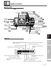
E
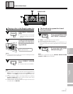
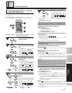
I/O INTERFACE
E I/O INTERFACE (For PD-AP1 only)
Terminal for connecting the controller (optional). The PD-AP1 is
capable of simultaneous control of up to 3 units of this model.
When using the optional controller, use the I/O interface with the
CONTROL IN jack.(Refer to 21 page)
(Be sure to use the supplied CD-DECK SYN-
CHRO control cord with the cassette deck.)
D CD-Deck synchro function
If you have a Pioneer cassette deck provided with the CD-Deck
synchro function, connect the CD-DECK SYNCHRO jacks of the
CD player and cassette deck. With this function, synchro record-
ing can be carried out between the player and deck.
÷ For details on connections and operation, refer to the operating
instructions supplied with the cassette deck.
÷ The CD-DECK SYNCHRO cable is not supplied with the CD
player.
÷ When CD-Deck synchro recording is carried out on several discs,
use the program playback function. (Refer to page 15 for details
of program playback.)
Note!!
In order to enable the CD-DECK SYNCHRO recording function, the
Output cable must be connected to the stereo amplifier.
CD
L
White
R
Red
A-1
Output cable
White
Red
OUT
IN
Stereo amplifier
Control cable
CD player
B
Optical fiber cable
CD-DECK SYNCHRO cable
R
L
R
L
CONTROL
OUT
C
To the CONTROL IN jack of
the Pioneer component
bearing the Î mark.
A-2
CD-DECK
SYNCHRO
D
Cassette deck
Control cable
C
Power cord
÷ Control input jack
÷ Control output jack
CONTROL
IN
OUT
DIGITAL
INPUT
OPTICAL
I/O
INTERFACE
R L
LINE OUT
CD-DECK
SYNCHRO
DIGITAL OUT
OPTICAL
COAXIAL
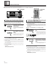
B Connecting to the DIGITAL OUT JACK
This unit can be connected to an amplifier equipped with an optical
digital jack or coaxial digital jack.
Note!!
No sound may be produced if optical connection are made with an
amplifier having different optical signal standard.
When using the OPTICAL DIGITAL OUT jack:
1. Remove the protective dust cap from this unit’s DIGITAL OUT
OPTICAL jack.
2. Use an optical fiber cable to connect the DIGITAL OUT OPTICAL
jack of this unit to the optical input jack of the amplifier.
÷ Align the plug of the optical fiber cable with the optical digital jack and
fully insert the plug to make a secure connection.
Use a separately sold optical fiber cable for the optical digital jack
connections.
Precautions concerning use of optical fiber cables
÷ Fully insert the optical fiber cable plugs all the way into the jacks.
÷ Be careful not to fold or crimp the cable. When coiling an optical fiber cable
for storage, make sure the diameter of the coil is 15 cm (6 in.) or larger.
÷ Use an optical fiber cable with a length of 3 m ( 10 ft.) or less.
÷ Protect the optical fiber cable plugs from scratches and dust.
÷ When the unit is not connected using an optical fiber cable, be
sure to keep the protective dust cap plugged into the optical digital
output jack at all times.
When using the COAXIAL DIGITAL OUT jack:
Use coaxial output cable to connect the COAXIAL DIGITAL OUT jack
of this unit to the coaxial digital input jack of the amplifier.
B
Coaxial output cable
COAXIAL