


3
1.6 Programming the PXDP
Now that you have identied the correct harness and dip-switch conguration
using the application guide, it is now time to program the interface.
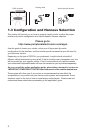
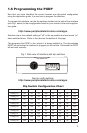
To program the interface, set the dip-switches located on the side of the interface
(see Fig.1 below) to the congguration listed for your vehicle in the online applica-
tion guide:
http://www.peripheralelectronics.com/apps
Switches are in their default setting of “off” in the up position and are turned “on”
when switched down. Refer to the chart on the bottom of this page.
This programs the PXDP to the vehicle it is being installed in. The dip-switches
MUST be set before the interface is plugged into the vehicle. Otherwise the PXDP
will not work correctly.
TOP VIEW
1 2
3
4
5
6
7
8
DIP
ON
DIN CONNECTOR / DIP SWITCH VIEW
22-PIN HARNESS VIEW
Fig.1 Side view of Interface with dip switches
Dip Switch Conguration Chart
1 2 3 4 5 6 7 8
Cong. #1 ON off off ON off off off ON
Cong. #2 ON off off off off off off ON
Cong. #3 off off off ON off off off ON
Cong. #4 off ON off off off off off ON
Cong. #5 ON ON off off off off off ON
Cong. #6 off off ON off off off off ON
Cong. #7 ON off ON off off off off ON
Cong. #8 off ON ON off off off off ON
Cong. #9 ON ON off ON off off off ON
http://www.peripheralelectronics.com/apps
See for cong settings: