


CN8240 & CN8260 Series Communications & Options
2
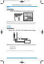
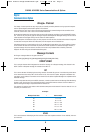
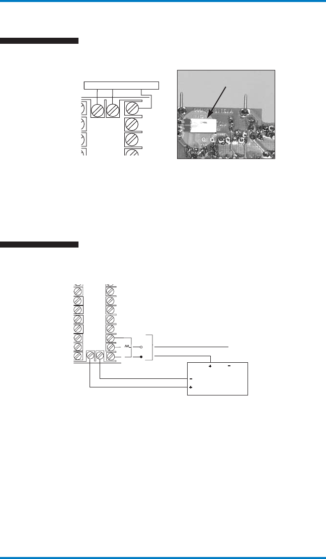
RS-485
Communications
1
2
3
1
1
12
13
14
23
24
4
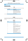
RCV
B(-)
XMT
A(+)
SIG GND
SIG GND
RS 232
RS 485
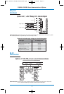
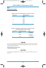
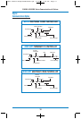
Option Description: Provides one-to-many communications.
Terminate the controller furthest from the computer by either connecting a 120-ohm, 1/4-watt resistor between ter-
minals 23 and 24 or using jumper 1 located on the underside of the communications board as shown above.
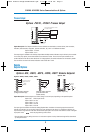
JMP 1
B(-) A(+) SIG GND
Option -C4: RS-485 (one-to-many) Communications
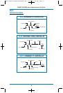
Transducer
Power Supply
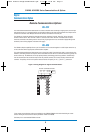
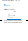
Options -XP1, -XP2, -XP3, -XP4: Transducer Power Supply
+
–
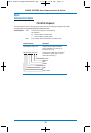
NOTE: FOR 2 WIRE RTD
JUMPER 18 & 20
3
12
13
14
15
16
17
18
8
9
1
0
19
2
0
21 22
4
5
6
7
T/C
+
–
RTD
MA
MV
V
SENSOR
INPUT
Option Description: The transducer power supply option provides power to remote transducers. The transducer
outputs, in turn, provide a signal to the controller input which can be scaled in the appropriate engineering units.
Option -XP1: 15 Vdc
Option -XP2: 12 Vdc
Option -XP3: 10 Vdc
Option -XP4: 5 Vdc
All options will provide at least 20 mA. The transducer circuitry is thermally protected from short circuits.
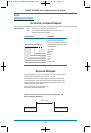
0 to1 volt out = 0 to100% RH
(6 to 30 Vdc input)
10002 Athena Omega:900M124U00.qxd 5/13/08 2:39 PM Page 5