


CN8240 & CN8260 Series Communications & Options
15
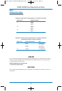
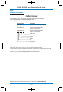
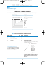
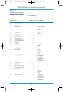
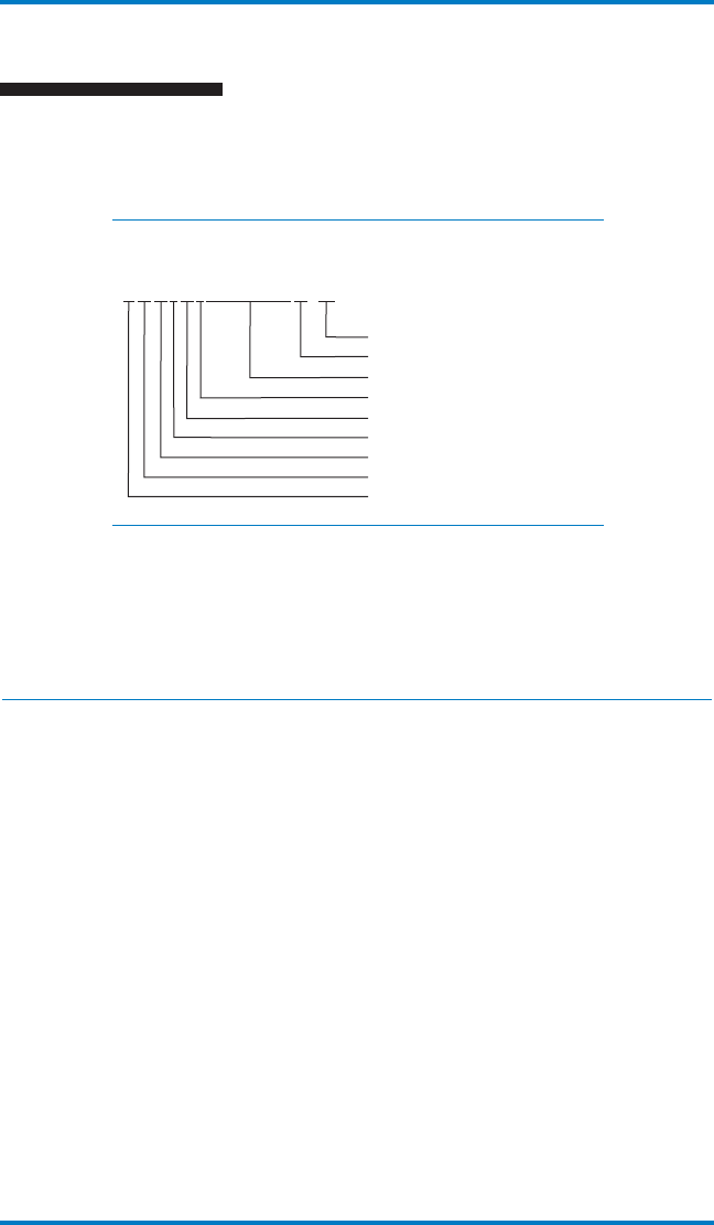
Request Message Description
%Ø1Ø1AØ1ØXXXXXXXXXXØ4<CR> Default load all parameters
has started.
%Ø2Ø1AØ2ØØ.ØØØØØØØØB6<CR> RTD low calibration on controller
#2 has started.
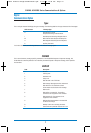
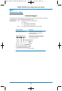
END CHAR
CHKSUM
DATA
STATUS
PARAM
TYPE
ZONE
ID
START CHAR
Digital
Communications Option
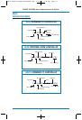
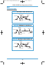
The Auxiliary Command Response:
The Auxiliary Command Response will be sent in response to an Auxiliary Command Request. Some examples are:
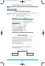
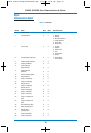
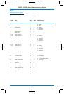
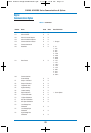
Table 1.Communications Parameter List (Omega+ Protocol)
Number Name Read Write Data Field Value
1 Controller Type X 0 3
2 Software Version X 0
3 Communications Version X 0
4 Status Byte X 0 This field contains the ASCII
representation of an 8-bit value
in which the bit assignments are as follows (starting
from the least significant bit):
X Process Input Error
X RAS Error
0 Always Zero
X Loop Break
X Alarm 1 Active
X Alarm 2 Active
0 Always Zero
0 Always Zero
If a bit at a location marked as “X”
is set, then the condition is TRUE.
For example, a “48.000” in the data field means that
both alarm 1 and alarm 2 are active and everything
else is FALSE.
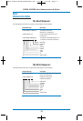
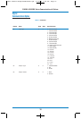
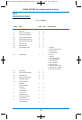
CN8240/CN8260 Parameter Codes
“X”s mark parameters that are supported by
the CN8240 and CN8260 and “O”s indicate
parameters that are not supported.
10002 Athena Omega:900M124U00.qxd 5/13/08 2:39 PM Page 18