


Incorrect driver polarity impairs system
performance and may damage the dri-
vers. All Meyer Sound loudspeakers are
shipped with the drivers in correct
alignment.
If the driver or circuit wiring has been
removed or disassembled it is essential
to check the polarity between adjacent
monitors and between drivers and
between adjacent loudspeakers.
POLARITY IN
ADJACENT LOUDSPEAKERS
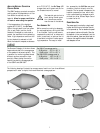
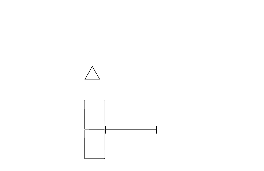
Use the following test procedure to veri-
fy the polarity between two adjacent
loudspeakers of the same type:
1. Position two loudspeakers adjacent to
each other.
2. Place a measurement microphone 3ft.
from the speakers and 3 to 4 feet
above the USM-1Ps, on the axis
between the speakers.
3. Connect a signal source to one speak-
er and note the frequency response
and overall level.
4. Apply the same signal to the second
speaker with the first speaker still
connected.
The polarity is correct if the frequency
response remains constant with a 5-6dB
SPL increase in amplitude. Broadband
cancellation (decreased overall level)
indicates polarity reversal.
Since polarity reversal causes
excessive driver excursion at
high source levels, use mod-
erate levels when conducting
these tests.
DRIVER POLARITY IN THE SAME USM-P
Use the following test procedure to veri-
fy polarity between drivers in the same
loudspeaker:
1. Place a monitoring microphone 1
meter from the front of the loud-
speaker at the midway point between
the high and low frequency drivers.
2. Connect a full range signal to the
loudspeaker and note the frequency
response.
The polarity is correct if the frequency
response is smooth through the
crossover region (800Hz to 1.5kHz).
Cancellation of 6dB or more in this
region indicates polarity reversal.
8
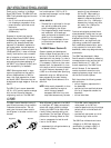
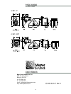
USM-P
Reference
USM-P
Under Test
3 Feet
VERIFYING POLARITY
!
TROUBLESHOOTING
This section suggests several possible
solutions to some common problems
encountered by USM-P users and is not
intended to be a thorough troubleshoot-
ing guide.
Qualified electronics technicians with
access to a test bench can request the
following documents from Meyer Sound:
Troubleshooting Guide, The Low
Frequency Driver Replacement
Procedure, and The High Frequency
Driver Replacement Procedure for the
USM-1P/100P.
If your difficulty persists, or if you sus-
pect the problem lies solely within the
USM-P, please contact Meyer Sound
Technical Support or return the unit to
the factory or nearest authorized service
center.
T
HE ON/TEMP. LED DOES NOT ILLUMI-
NATE, THERE IS NO AUDIO, AND THE
POWER SUPPLY FAN IS OFF
.
1. Make sure the AC power cable is the
correct type for the regional voltage
and that it is securely connected to
the AC inlet then unplug and recon-
nect the AC cable.
2. Use an AC voltmeter to verify that
the AC voltage is within the ranges
88-264V, 47-63 Hz.
T
HE ON/TEMP. LED IS ILLUMINATED
BUT THERE IS NO SOUND
.
1. Verify that the audio source (mixer,
EQ, delay) is sending a valid signal.
2. Make sure the XLR cable is securely
fastened to the XLR audio input con-
nector.
3. Verify that the XLR cable is function-
ing by substituting another cable or
by using the cable in question in a
working system.
4. Send the audio signal to another
speaker to insure signal presence and
that the level is within the proper
range. Turn the source level down
before reconnecting the audio input
and increase the level slowly to avoid
a sudden blast of sound.
5. If possible, monitor the audio source
with headphones.
HUM OR NOISE IS PRODUCED BY THE
SPEAKER
.
1. Disconnect the audio input. If the
hum ceases, the noise originates
somwhere earlier in the signal path.
If the noise persists, the problem is
within the USM-P.
2. Make sure the XLR cable is securely
fastened to the XLR audio input con-
nector.
3. Send the audio signal to another
speaker to insure signal presence and
that the level is within the proper
range. Turn the source level down
before reconnecting the audio input
and increase the level slowly to avoid
a sudden blast of sound.
5. Hum or noise can be produced by a
ground loop. Since the USM-P is
effectively ground-lifted, this should
not occur unless grounds are extreme-
ly different voltages.