


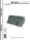

Thank you for investing in the Meyer
Sound USM-P Series. The USM-100P and
USM-1P self-powered stage monitors are
composed of:
• one 15-inch cone driver and one 3-
inch diaphragm compression driver;
• phase-corrected, optimized control
electronics;
• a two-channel amplifier
(350Wrms/ch).
Compared to conventional monitor
designs, Meyer Sound’s USM-P Series
loudspeakers are uniquely capable of
producing flat phase and amplitude
response, full bandwidth reproduction
and a near-perfect impulse response.
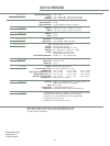
The USM-P boasts a maximum output of
132dB peak SPL at 1 meter with excep-
tionally low distortion and a noteable
lack of coloration at all amplitude lev-
els. An additional benefit of the design
engineering and system packaging of
the USM-P is its improved linearity and
lower susceptibility to feedback.
USM-P Series systems excel in stage
monitoring applications that require
efficient response down to 30Hz for
clean, high level reproduction of bass
and drums. USM-P Series monitors can
be deployed as stage wedges or flown as
side-fill.
The USM-1P horn's narrow beamwidth
(45°H x 45°V) permits precise coverage
with minimal interaction between
neighboring monitors. The USM-100P
horn's wider pattern (100°H x 40°V)
provides broad coverage in either wedge
or flown applications.
DESIGN BENEFITS:
• The amplifier is optimized for the sys-
tem, providing substantial power
without endangering the drivers.
• The integrated design simplifies setup
and installation, eliminates amp
racks, and extends the durability and
reliability of the loudspeaker.
• The gain structure between the con-
trol electronics and amplifier is per-
fectly matched.
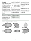
THE USM-P HORNS: CONSTANT-Q
Constant research and development
efforts at Meyer Sound have led to the
solution of the most difficult problems
associated with horn design. In order to
appreciate the significance of this work,
it is necessary to define an often misun-
derstood term: the beamwidth of a horn
is the angle at which the sound pressure
at a given frequency decreases to half
(-6dB) its on-axis amplitude. Specifying
beamwidth using the -6dB points has
been proposed as the audio industry
standard; Meyer Sound adheres to this
definition.
NOTE: Unfortunately, beamwidth is often
used to describe the angle at
which the sound pressure
decreases 10dB from its on-axis
amplitude because many listeners
perceive this as a decrease to
half the SPL. When reading a
beamwidth specification, it is
essential to determine whether it
refers to the -6 or -10dB points
because they indicate very differ-
ent results: the -10dB points
yield a wider angle.
Previous technologies produced horns
whose beamwidth varied over the oper-
ating frequency range. These horns also
displayed nonuniform frequency
response within, and significant side
lobe energy outside their beamwidth.
Both undesirable characteristics, partic-
ularly prevalent for horns with a wide
beamwidth, make array design extremely
problemactic.
The USM-P was developed in Meyer
Sound's anechoic chamber by measuring
coverage patterns using angular and fre-
quency resolutions of 1° and 1/36
octave, respectively. The USM-P horns
exhibit Constant Q: the beamwidth
remains consistent across the horn's
operating frequency range in both the
vertical and horizontal planes.
Both horns share the following remark-
able attributes:
• uniform frequency response within
the beamwidth
• rapid and uniform amplitude attenua-
tion for all frequencies outside the
beamwidth
• minimal side lobes
4
USM-P: INTRODUCTION AND TECHNICAL ADVANTAGES
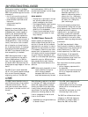
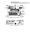
AC POWER
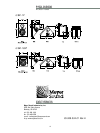
The USM-P uses a PowerCon locking 3-
pole AC mains connector that prevents
inadvertent disconnection. The unit
must have the correct power cord for
the AC power in the area in which it will
be used.
When AC power is applied to the USM-P,
an Intelligent AC
tm
supply automatically
selects the correct operating voltage,
allowing the USM-P to be used interna-
tionally without manually setting volt-
age switches. The Intelligent AC supply
performs the following protective func-
tions to compensate for hostile condi-
tions on the AC mains:
• suppresses high voltage transients up
to several kilovolts
• filters EMI (radio frequencies and
noise present on the AC line)
• sustains operation during low-voltage
periods, which minimizes audio dis-
continuity
• provides soft-start power-up, which
eliminates high inrush current
The USM-P can withstand continuous
voltages up to 264V and allows any
combination of voltage to GND (i.e.
Neutral-Hot-GND, Hot-Hot-GND).
Engagement
2
1
2
1
3
Separation