


Operating Instructions
Meyer Sound Laboratories, Inc.
2832 San Pablo Avenue
Berkeley, CA 94702
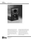
UPA-2C
Loudspeaker
Rigging
pull. Load directions other than straight can result in a
significant reduction in breaking strength.
All rigging load ratings are also specified for cabinets in
new condition. Age, wear or damage to the product can
greatly reduce its rating. Accordingly, all products should
be inspected on a regular basis. Any worn, damaged or
deformed rigging components should be immediately
removed from service and replaced.
All Meyer Sound products must be used in accor-
dance with local, state, federal and industry regula-
tions. It is the owner’s and/or user’s responsibility to
evaluate the suitability of any rigging method and
product for their particular application. All rigging
should be done by competent professionals.
The UPA-2C loudspeaker has four steel rigging brackets
internally mounted as an integral part of the cabinet
design and the cabinet is supplied with either aircraft pan
fittings (ring and stud) or
3
⁄
8
"-16 nut plates, according to
user preference. A flat plate is supplied when no rigging
hardware is specified. All three plate types are held in
place by six phillips-head machine screws and can be
interchanged at any time. The handles on the UPA-2C
cabinet are provided for moving and carrying the loud-
speaker and are not to be used for rigging purposes.
The rigging hardware is designed so that a single point
can support the normal load for the cabinet. In the case
of the UPA-2C with aircraft pan fittings, the recom-
mended maximum load is 420 lbs (190 kg). This working
load is one-fifth the cabinet breaking strength, which is
the minimum load that the cabinet will withstand before
failing. All load ratings are based on a straight tensile
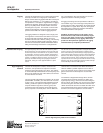
The UPA-2C is a high-Q loudspeaker, designed to provide
precise coverage control and minimize unwanted reflec-
tions. Horizontal arrays should always be tight-packed (ad-
jacent cabinet sides touching) to assure smooth transitions
between units. When arraying units above one another to
extend vertical coverage, make certain that each UPA-2C
operates into its own coverage area with minimum overlap
between units. Array performance is best verified and opti-
mized with Meyer Sound’s SIM System II.
Placement and Arraying The high frequency horn of the UPA-2C adds very well in
the horizontal axis, and the apparent sources of both high
and low frequencies in the UPA-2C are co-planar in terms
of propagation. For these reasons, multiple loudspeakers
may be built into an array which behaves acoustically as a
section of a radiating spherical surface. Such arrays offer
precisely controlled coverage and propagate coherent
wavefronts, acting as a close approximation to a point
source.
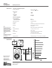
The UPA-2C loudspeaker contains, mounted in the
enclosure, a DC protection and response correction
network for the high-frequency horn driver. The network
is mounted directly behind the MS-12 low-frequency cone
driver on the inside rear face of the cabinet, and is wired
in series with the horn driver.
The circuit board is fitted with five terminals, two of which
(labeled AMP- and AMP+) are wired to the EP-4 connec-
tor pins 3 and 4. The other terminals (labeled FLAT and
16KPK), provide two options for tailoring the system’s
response. With the high driver common (green) wire
connected to the FLAT terminal, the UPA-2C high-fre-
quency response is nominally flat to 18 kHz. When the
common wire is connected to the 16KPK terminal, the
UPA-2C exhibits a peaked response in the 16 kHz re-
gion. This response may be useful for overcoming propa-
gation losses when far-field response is a dominant
concern.
The UPA-2C is shipped with the high driver common
connected for flat response. Should you desire more
high-frequency energy, remove the six bolts holding the
MS-12 in place, pull the MS-12 up and out of the cabinet,
and move the green wire from the FLAT terminal to the
16KPK terminal. Be careful not to disturb the other wires
to the network board or EP connector. When replacing
the MS-12, be certain to tighten the six bolts evenly.
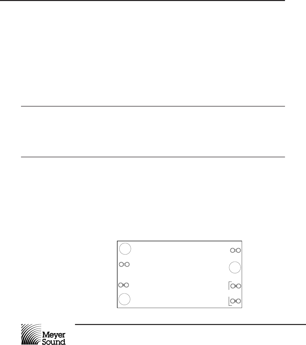
High Frequency
Network
AMP+
WHT
AMP -
GRN
TESTED:_________
DATE:___________
DRVR+
WHT
FLAT
DRVR-
GRN
©1992 Meyer Sound Y-1PD PCB
Assy. # 24.052.103._________Rev_________
16KPK
UPA-2C High Frequency Network Circuit Board