


Operating Instructions
Meyer Sound Laboratories, Inc.
2832 San Pablo Avenue
Berkeley, CA 94702
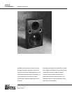
UPA-2C
Loudspeaker
Amplifier Requirements The UPA-2C requires a professional quality two-channel
power amplifier rated at 350 watts per channel continuous
into 8 ohms. (If two UPA-1Cs are to be operated in parallel
from the amplifier, it should be capable of driving 4 ohms.)
Amplifiers of lower power will not allow the full power and
headroom of the UPA-2C system to be realized (though this
may be acceptable in applications where high pressure
levels are not required). Conversely, amplifiers rated at
significantly more than 350 watts per channel into 8ohms
may endanger the loudspeaker,and is not recommended.
For further information on power amplifiers, please refer to
Power Amplifier Criteria, a Technical Note available from
Meyer Sound.
Note: If you are using standard Meyer Sound loudspeaker
cables and adapters, simply connect the female end of
the loudspeaker cable to the UPA-2C, the male end of the
cable to the Meyer Sound pigtail adapter, and the banana
connectors of the adapter to your amplifier outputs. In
making connections between the UPA-2C and the amplifier,
be sure to connect the 12-inch driver to the Lo channel, and
the horn driver to the Hi channel.
The adapter banana plugs are color-coded as follows:
Red – Low frequency driver
Black – High frequency driver
For connections between the M-1A and the power amplifier,
refer to the M-1A Operating Instructions
■ If the polarity of the horn driver is reversed, a trough will
appear in the response curve, centered near 1600Hz. If
in doubt, reverse the polarity of the Hi amplifier output
while you watch the analyzer display.
2.Multiple cabinet arrays
Each cabinet should first be tested as above.
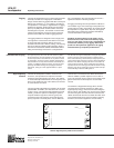
■ Connect one loudspeaker in the array and advance the
pink noise to a convenient measuring level. Position
the measuring microphone on the axis between the first
loudspeaker and the cabinet adjacent to it, and about six
feet distant. Note the frequency response and overall
level.
■ Leaving the first loudspeaker connected, connect the
adjacent one and observe the analyzer display. The
entire curve should jump up in level, indicating correct
addition between the loudspeakers. A polarity reversal
between the loudspeakers will show up as severe
broadband cancellation.
■ Similarly, connect the rest of the cabinets in the array
one by one, looking for correct addition as each
loudspeaker is connected. (It will be necessary to
reposition the microphone.)
Note: A polarity reversal within the system can result in
severe damage to the components. It is strongly
recommended that polarity testing be done at low levels
and with the appropriate equipment.
Verifying Polarity
All Meyer Sound loudspeakers are thoroughly tested in all
stages of manufacture, and correct polarity of individual
cabinets is assured. However, accidental polarity reversal
is possible when there are multiple amplifier connections.
A single cabinet which is out of phase with the rest of the
system will cause severe cancellation, resulting in a
noticeable decrease in SPL and possible component
damage.
The “phase-popper” type of speaker phase checkers
cannot reliably be used to test for correct polarity of the
low and high drivers of the UPA-2C. However, because the
UPA-2C is phase-corrected through crossover, Meyer
Sound’s SIM
®
System II or many of the portable spectrum
analyzers can be used, with a pink noise sourse, to test for
driver polarity as follows:
1. Single cabinets
First, verify polarity of the woofer by connecting a 9 volt
battery at the end of the loudspeaker cable.
EP Connector Battery
Pin 1 +terminal
Pin 2 - terminal
■ The woofer cone should move outward. Connect the
speaker cable to the amplifier.
■ Input the pink noise source to the M-1A and advance the
M-1A Level control to a convenient measuring level.
■ Standing in front of the loudspeaker, position the
analyzer microphone directly between the horn and the
12-inch driver, at right angles to the cabinet face, and
about 20 inches in front of the UPA-2C.
Connections The UPA-2C is a biamplified system and must be used with
the M-1A Control Electronics Unit. The M-1A functions as
an active crossover, dividing the input signal into high- and
low-frequency components.
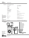
The connection terminals of the low- and high-frequency
drivers appear on a single P-type 4-pin connector located
on the rear of the UPA-2C cabinet. The pin assignments for
this connector are:
Pin 1 – 12-inch driver, hot
Pin 2 – 12-inch driver, common
Pin 3 – horn driver, common
Pin 4 – horn driver, hot
(When the cabinet is fitted with an EP-5 connector, Pin 5 is
unconnected.)
The minimum wire size for connections between the
UPA-2C and the power amplifier should be 14 gauge.