


MILO 120 Specifications
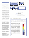
1. The low-frequency power response of
the system will increase according to
the length of the array.
2. Recommended maximum operating
frequency range. Response depends
upon loading conditions and room
acoustics.
3. Measured with 1/3 octave frequency
resolution at 4 meters.
4. Measured with music at 1 meter.
5. At these frequencies, the transducers
produce equal sound pressure levels:
560 Hz for the low-mid and mid-high
and 4.2 kHz for the mid-high and
very-high frequency drivers.
6. Power handling is measured under
AES standard conditions: transducer
driven continuously for two hours with
band limited noise signal having a 6 dB
peak-average ratio.
7. To eliminate interference at short
wavelengths, the two 12-inch
drivers work in combination at low
frequencies (60 Hz – 180 Hz). At mid
frequencies (180 Hz – 560 Hz) only one
cone driver is fed from the crossover
to maintain optimal polar and
frequency response characteristics.
8. The three drivers are coupled to a
constant-directivity horn through
a proprietary acoustical combining
manifold (REM).
9. Amplifier wattage rating is based
on the maximum unclipped burst
sine-wave rms voltage the amplifier
will produce in to the nominal load
impedance low, mid and very high
channels 67 V rms (95 V pk) into 4, 6
and 8 ohms.
10. AC power cabling must be of sufficient
gauge so that under burst current RMS
conditions, cable transmission losses
do not drop voltage below specified
operating range at the speaker.
meyer sound laboratories inc.
2832 San Pablo Avenue
Berkeley, CA 94702
T: +1 510 486.1166
F: +1 510 486.8356
techsupport@meyersound.com
www.meyersound.com
MILO 120 - 04.142.003.01 A
Copyright ©2004
Meyer Sound Laboratories Inc.
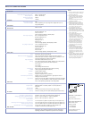
Operating Frequency Range
2
Free Field Frequency Response
3
Phase Response
Maximum Peak SPL
4
Dynamic Range
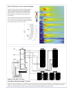
Horizontal Coverage
Vertical Coverage
Low/Low-Mid Frequency
7
Mid-High Frequency
Very-High Frequency
8
Type
Maximum Common Mode Range
Connectors
Input Impedance
Wiring
DC Blocking
CMRR
RF Filter
TIM Filter
Nominal Input Sensitivity
Input Level
Type
Output Power
THD, IM, TIM
Load Capacity
Cooling
Connector
Automatic Voltage Selection
Safety Agency Rated Operating Range
Turn-on and Turn-off Points
Current Draw:
Idle Current
Max Long-Term Continuous Current (>10 sec)
Burst Current (<1 sec)
10
Ultimate Short-Term Peak Current Draw
Inrush Current
60 Hz - 18 kHz
65 Hz - 17.5 kHz ±4 dB
750 Hz - 16 kHz ±30°
138 dB
>110 dB
120°
Varies, depending on array length and configuration; 20° for
single loudspeaker
560 Hz, 4.2 kHz
Two 12" cone drivers with neodymium magnets
Nominal impedance: 4
Ω
Voice coil size: 4"
Power-handling capability: 1200 W (AES)
6
One 4" compression driver
Nominal impedance: 8 Ω
Voice coil size: 4"
Diaphragm size: 4"
Exit size: 1.5"
Power handling capability: 250 W (AES)
6
on REM
Two 2" compression drivers
Nominal impedance: 12 Ω
Voice coil size: 2"
Diaphragm size: 2"
Exit size: 0.75"
Power handling capability: 100 W (AES)
6
on REM
Differential, electronically balanced
±15 V DC, clamped to earth for voltage transient protection
Female XLR input with male XLR loop output or VEAMall-in-one
connector (integrates AC, audio and network)
10 kΩ differential between pins 2 and 3
Pin 1: Chassis/earth through 220 kΩ, 1000 pF, 15 V clamp network
to provide virtual ground lift at audiofrequencies
Pin 2: Signal +
Pin 3: Signal -
Case: Earth ground and chassis
None on input, DC blocked through signal processing
>50 dB, typically 80 dB (50 Hz–500 Hz)
Common mode: 425 kHz
Differential mode: 142 kHz
Integral to signal processing (<80 kHz)
0 dBV (1 V rms, 1.4 V pk) continuous is typically the onset of
limiting for noise and music
Audio source must be capable of producing a minimum of +20 dBV
(10 V rms, 14 V pk) into 600 Ω inorder to produce maximum peak
SPL over the operating bandwidth of the loudspeaker
Complementary power MOSFET output stages (class AB/H)
3560 W (1125 W x 2 channels, 750 W x 1 channel, 560 W 1 x
channel)
9
<.02%
4 Ω low and low-mid, 8 Ω mid, 6 Ω very-high channel
Forced air cooling, four fans (two ultrahigh-speed reserve fans)
250 V AC NEMA L6-20 (twistlock) inlet, IEC 309 male inlet, or VEAM
Automatic, two ranges, each with high-low voltage tap
95 V AC – 125 V AC, 208 V AC - 235 V AC; 50/60 Hz
85 V AC – 134 V AC; 165 V AC - 264 V AC
1.1 A rms (115 V AC);0.55 A rms (230 V AC);1.3 A rms (100 V AC)
11.2 A rms (115 V AC);5.6 A rms (230 V AC);12.9 A rms (100 V AC)
14.4 A rms (115 V AC);7.2 A rms (230 V AC);16.6 A rms (100 V AC)
32 A pk (115 V AC);16 A pk (230 V AC);37 A pk (100 V AC)
7 A (115 V AC and 110 V AC); 10 A (230 V AC)
Equipped for two conductor twisted-pair network, reporting all
operating parameters ofamplifiers to operator’s host computer.
Notes
:
Acoustical
1
Coverage
Crossover
5
Transducers
Audio Input
Amplifiers
AC Power
RMS Network
EuropeanOffice:
MeyerSoundLab.GmbH
CarlZeissStrasse13
56751Polch,Germany
MadebyMeyerSoundLaboratories
Berkeley,CaliforniaUSA