


Signal Flow for a Typical
Integrated Reinforcement System
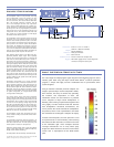
Because the MILO 120 loudspeaker is compatible with most other Meyer Sound reinforcement loudspeakers, sound designers have maximum
freedom to customize systems for their needs. This block diagram illustrates the signal flow for a typical integrated sound reinforcement
system using 10 MILO cabinets per side for the main arrays, and two MILO 120 loudspeakers used as downfill.
Digital Delay
2 In x 6 Out
Digital Delay/EQ
LD-3
Channel A
IN SUB OUT
CH 1 OUT
CH 2 OUT
CH 3 OUT
Channel B
IN SUB OUT
CH 1 OUT
CH 2 OUT
CH 3 OUT
Channel A
INSERTS SENDS
IN SUB OUT
Full Range
IN CH 1 OUT
Post Array
IN CH 2 OUT
Post Array
IN CH 3 Post HPF
Channel B
INSERTS SENDS
IN SUB OUT
Full Range
IN CH 1 OUT
Post Array
IN CH 2 OUT
Post Array
IN CH 3 Post HPF
(10) MILO
(10) MILO
(2) MILO 120 (2) MILO 120
W/ MILO 120-I INSE
RTS
(OPTIONAL)
W/ MILO 120-I INSE
RTS
(OPTIONAL)
(6) 700-HP SUB
(6) 700-H
P SUB
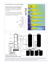
MILO 120 Vertical Splay and Coverage
These illustrations show how the splay between adjacent
cabinets in a MILO/MILO 120 array may be adjusted to
tailor coverage for a specific venue. The MAPP Online
plots illustrate the vertical directivity characteristics of
this example array, with a section view of the venue
superimposed.
The top six cabinets (MILO) are splayed at small angles to
throw farther through coupling and cover the back of the
venue. The bottom two cabinets (MILO 120) are splayed at
wider angles to better cover the near field.