


15
CHAPTER 4
RMS is a real-time monitoring system that connects Meyer
Sound self-powered loudspeakers with a Windows-based
PC at the sound mix position or other location. Optional
RMS software delivers extensive status and system perfor-
mance data from every installed loudspeaker. M’elodie is
RMS-ready and fitted standard with an RMS communica-
tion board installed in its user panel.
RMS allows the monitoring of amplifier voltages, limiting
activity, power output, temperature, driver status, warning
alerts, and other key data for up to 62 loudspeakers without
a network repeater. Data is updated two to five times per
second.
NOTE: Optional loudspeaker Mute and Solo
functions are helpful for acoustic setup or
troubleshooting. A jumper is installed in the RMS
communication board inside the M’elodie ampli-
fier to enable Mute and/or Solo functionality. To use
these features, the software needs to be enabled.
NOTE: The RMS software allows you to
disable Mute and Solo functions to eliminate
any chance of an operator error (a muting error, for
example). However, these functions can be disabled
permanently by removing the jumper in the RMS
communication board.
NOTE: RMS does not control AC power.
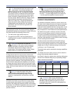
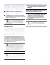
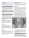
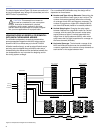
Loudspeakers are identified on the network by Node Names
assigned during a one-time “commission” into the RMS
database that resides on your computer (as a part of the
software), as shown in Figure 4.1. This information is per-
manently retained on each RMS communication board and
in the computer RMS database until you modify it. Loud-
speaker View labels can be modified at any time, allowing
you to customize how you view the data.
Figure 4.1. Commissioning a M’elodie loudspeaker using RMS.
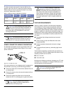
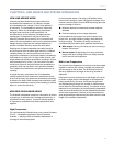
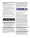
Back and forth communication between the RMS software
and the M’elodie makes identifying and matching loudspeak-
ers and icons easy. Pressing the “service” button on the
M’elodie loudspeaker’s RMS module will help quickly identify
the M’elodie in the RMS software window; an icon corre-
sponding to its Node Name will appear on screen. In addi-
tion, clicking on the icon’s Wink command will turn on the
LED labeled “Wink” on the M’elodie’s RMS module. This way
any M’elodie can be easily identified from the RMS software.
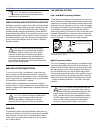
Figure 4.2. M’elodie RMS icon
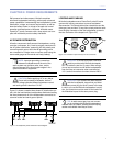
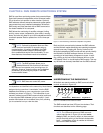
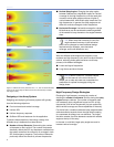
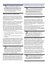
UNDERSTANDING THE RMS MODULE
M’elodie’s user panel contains an RMS communications
module, as shown in Figure 4.3.
Network
Service
Wink
Reset
Activity
Remote Monitor System
RMS3
Firmware
Looping Audio Input
10k Ω Balanced
Input Loop
AC LOOP OUTPUT
115/230V
~ 50-60 Hz
10A RMS @115V
~
12.5A RMS @230V~
Class 1 Wiring
!
AC INPUT RATING
115/230V
~ 50-60 Hz
5A RMS @115V
~
2.5A RMS @230V~
1500W BURST MAX
Figure 4.3. The RMS communications module
The RMS module has three LEDs and two buttons. Their
functions are described on the following page.
NOTE: The LEDs and buttons on RMS communi-
cation board shown in Figure 4.3 are used exclu-
sively by RMS, and have no effect on the acoustical
and/or electrical activity of the M’elodie loudspeaker
itself — unless Mute or Solo is enabled at the board
and from the RMS software.
CHAPTER 4: RMS REMOTE MONITORING SYSTEM