


12
CHAPTER 3
NOTE: For details on the M’elodie loud-
speaker’s audio input characteristics and
amplification, see Appendix C.
AMPLIFICATION AND PROTECTION CIRCUITRY
M’elodie is powered by Meyer Sound MP-1/M’elodie ampli-
fier modules in a three-channel amplifier configuration with
a total power of 1275 watts (2550 watts peak). The MP-1/
M’elodie amplifier utilizes complementary-power MOSFET
output stages (class AB/H). All the specific functions for the
M’elodie loudspeaker such as crossover points, frequency
and phase response, and driver protection are determined
by the control card installed in one of the MP-1/M’elodie
amplifier modules.
CAUTION: Please note that M’elodie and
other Meyer Sound loudspeaker amplifiers
are different. Specific functions for each model,
such as crossover points, frequency and phase
correction and driver protection are determined by
the control cards installed inside the amplifier. Do
not exchange amplifiers between M’elodie and other
Meyer Sound loudspeakers.
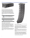
M’ELODIE INTERCONNECTIONS
The two 4-ohm, 8-inch, low-frequency cone drivers are
each powered with 500 watts from two MP-1 channels of
the three-channel M’elodie amplifier. The 3-inch diaphragm,
8-ohm, high-frequency compression driver is powered with
275 watts from the third MP-1 channel.
All Meyer Sound loudspeakers are tested and shipped
with the drivers in correct alignment. If a driver needs to be
replaced, make sure the replacement is reinstalled with the
correct polarity.
CAUTION: Failure to connect a replacement
driver using the proper polarity will result
in severe degradation in frequency and phase
response and can harm the drivers and amplifier.
CABLING
The M’elodie system uses three separate cables and con-
nectors per cabinet for the AC line current, signal, and RMS
data. However, the three can be consolidated to create a
“multi-cable” by looming them together for quick connec-
tion to each cabinet.
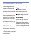
THE LIMITING SYSTEM
Low- and Mid-Frequency Limiters
The M’elodie loudspeaker’s left and right 8-inch cone driv-
ers are powered by separate amplifier channels, each with
a detector but routed to one limiter; the limiter tracks both
channels and uses the higher of the two values to engage.
By limiting both amplifier channels equally, any anomalies
in the frequency range shared by the drivers are elimi-
nated during limiting. The lower limit LED on the user panel
indicates limiting activity for these two drivers. When the
level for both low channels returns to normal — below the
limiter’s threshold — the limiter will cease operation.
Network
Service
Wink
Reset
Activity
Remote Monitor System
RMS3
Firmware
Looping Audio Input
10k Ω Balanced
Input Loop
AC LOOP OUTPUT
115/230V
~
50-60 Hz
10A RMS @115V
~
12.5A RMS @230V
~
Class 1 Wiring
!
AC INPUT RATING
115/230V
~
50-60 Hz
5A RMS @115V
~
2.5A RMS @230V
~
1500W BURST MAX
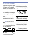
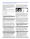
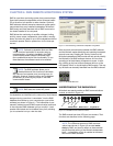
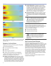
Figure 3.4: The limit LEDs on the user panel indicate high-frequency and
low-frequency limiter activity
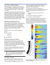
High-Frequency Limiter
The 3-inch diaphragm, high-frequency compression driver
is powered by a single channel with its own detector. The
upper Limit LED is used to indicate any limiting activity for
the high-frequency driver. When engaged, the limiter not
only protects the driver, but also prevents signal peaks
from causing excessive distortion in the amplifier channel,
preserving headroom and maintaining smooth frequency
response at high levels. When the level returns to normal
— below the limiter’s threshold — the limiter will cease
operation.
CAUTION: The limit LEDs indicate when the
safe power level is exceeded. If any channel
on a system of M’elodie loudspeakers begins to limit
before reaching the required sound pressure level
(SPL), consider adding more loudspeakers to satisfy
the SPL requirements. This will avoid exposing the
drivers on that channel to excessive heat and/or
excursion, reducing the life-span of the drivers.
high-frequency LED (yellow)
low-frequency LED (yellow)