


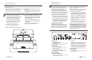
AFFIX THE iPOD-DEVICE SUPPORT
TO THE KID TOP COVER
IMPORTANT:
A
ffix the iPod-device support before inserting the
i
Pod-device into the dock connector (4).
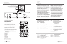
1. Remove the iPod-device support (1) from its
bubble wrap package.
2. The bracket bar has two thumbscrews (2).
Position these screws over the thumbscrew
holes in the KID top cover.
Orientation: The round black rubber pad (3)
on the iPod-device support faces the front of
the chassis (5).
4. Screw the iPod-device support thumbscrews
into the thumbscr
ew holes by hand.
Affix the iPod-device Support to the KID Top Cover
I
nstall the Battery in the KID Remote
Placement Considerations
Kr
ell
/Papa Dock 5
The KID remote control uses one CR2025 lithium
battery which is included with the shipment.
To open the battery compartment on the back of
the remote control:
1. Place the remote face down on the table.
2. Use your thumbnail or a small jeweler’s or eye-
glass screwdriver to move the small tab
toward the center of the remote, while using
your index fingernail or screwdriver to pull
down gently on the slot to the right of the tab.
The battery compartment slides out.
Before installing the KID or the Papa Dock into
your system, please review the following guide-
lines for the proper location of the components.
This will facilitate a clean, trouble-free installation.
Positioning the components
in the listening ar
ea
Place the KID and the Papa Dock on a firm, level
surface, away from excessive heat, humidity, or
moisture. These components do not require a
special rack or cabinet for installation.
Place the Papa Dock as close to the loudspeakers
as possible and keep the loudspeaker cable
length to a minimum. Loudspeaker cable adds
impedance to the load that the amplifier must
drive, regardless of the cable's gauge. Krell ampli-
fiers drive the lowest impedances with ease, but
long loudspeaker cables reduce the maximum
power that is deliver
ed to the loudspeakers.
Component Ventilation
The KID requires ventilation clearance:
—
at least eight inches (20 cm) above (to accom-
modate the iPod-device)
— the ventilation grids on the bottom of the KID
chassis must be unobstructed.
3. Place the battery plus side up in the battery tray.
4. Slide battery compartment back into the
remote until you hear a click.
The remote control is ready for operation.
Notes. Do not use a knife or other sharp objects to
open the battery compartment; to avoid scratching
the remote control finish.
Replace batteries when the remote control functions
becomes intermittent. Remove batteries if the remote
control is not to be used for a long period of time.
Battery leakage can damage the remote control.
INSTALL THE BATTERY
IN THE KID REMOTE
PLACEMENT CONSIDERATIONS
1
2
2
3
4
5
2
4
3
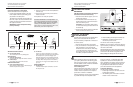
FIGURE 1 The iPod-device Support
Connecting the Papa Dock to Your System
A
C Power Guidelines for the Papa Dock
Papa Dock Back Panel Connections
8 Krell
/Papa Dock
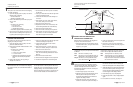
AMPLIFIER CHANNEL OUTPUTS
16 Left and Right Outputs
T
wo channel outputs via 5-way binding posts.
VIDEO OUTPUTS
17 Composite Video Output
One composite video output with an RCA connector.
18
S-Video Output
One S-Video output with a DIN connector.
REMOTE CONNECTIONS
19 Comm Port RS-232 Connector
Sends software updates directly to the KID using an
exter
nal computer contr
ol system.
20 12 VDC Out
Sends a 12 V power on/off signal via a 12 V trigger
cable to other Kr
ell components and to other devices
that incorporate 12 V power on/off trigger input.
When the Papa Dock is in the operational mode and
a trigger is enabled, the 12 VDC Out provides 12 V of
DC output. When the Papa Dock is in the stand-by
mode or off, or if a trigger is not enabled, the DC out-
put is 0 V.
POWER CONNECTION
21 IEC Connector
A standar
d male IEC power connector
, for use with
the AC power cord.
C
onnect the Papa Dock to Your System
With the KID docked onto the Papa Dock:
1
. Connect the loudspeaker cables to the Papa
Dock amplifier channel output binding posts
(16) located on the back panel.
The binding post terminals accept spade lugs,
bare wire, or pins. Use the red terminal for the
positive connection and the black terminal for
the negative connection.
IMPORTANT: Tighten loudspeaker binding
posts by hand only.
5. Plug the AC power cord into the amplifier’s IEC
connector (21).
6. Plug the other end of the AC power cord into
the AC wall outlet.
The amplifier is now ready for operation.
CONNECTING TO YOUR SYSTEM, continued
L
EFT OUTPUT
R
IGHT OUTPUT
R
S-232 IN
12VDC
OUT
30 mA
MAX.
COMPOSITE
S-VIDEO
VIDEO OUT
PAPA DOCKPAPA DOCK
KRELL INDUSTRIES, INC.
45 CONNAIR ROAD
O
RANGE, CT 06477-3650
USA
5
0/60 Hz
N
O USER SERVICEABLE PARTS INSIDE
MADE IN USA
16
16
17
18
19
20
21
FIGURE 7 Papa Dock Back Panel Connections
AC Power Guidelines for the Papa Dock. Krell
recommends operating the Papa Dock amplifier
from a dedicated 15-amp AC power line. Please
contact your Krell dealer, distributor, or Krell
before using any devices designed to alter or sta-
bilize the AC power for the Papa Dock.