


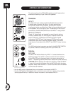
CONTROLS AND CONNECTIONS
The audio section of the EON15 G2 includes powerful features that
enhance the flexibility of your EON15 G2 speakers.
Connectors
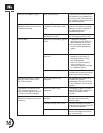
INPUT 1
This balanced input accepts a standard XLR (female) connector.
A broad range of signals (-44 dBu to +20 dBu nominal) from
microphones, audio mixing consoles, and electronic musical
instruments may be connected here. When using a single audio input
to the speaker, this is the input to use. The sensitivity of this input is
controlled by the MIC/LINE SWITCH and the INPUT 1 rotary control.
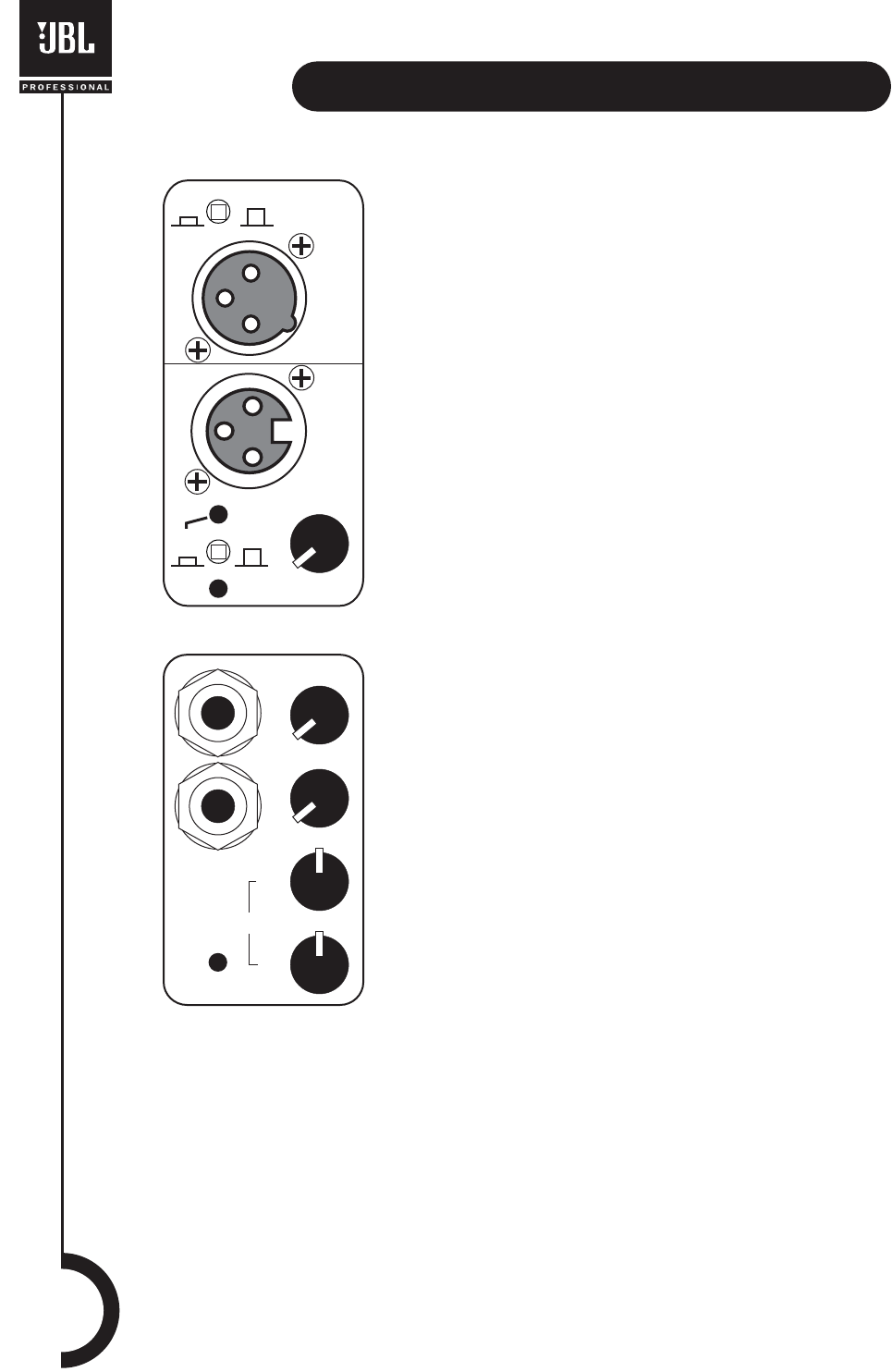
INPUT 2 & INPUT 3
These 1/4” phone jacks are intended for use with audio devices
including cassette tape, CD, MP3 players, computer sound-card
outputs, electronic keyboards, and electric/acoustic musical
instruments. INPUTS 2 and 3 are balanced (TRS) but will accept
unbalanced inputs with no special adapters needed. The level of
these inputs is controlled by the INPUT 2 and INPUT 3 rotary controls.
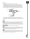
OUT
This XLR (male) output connector works with the MIX/LOOP SWITCH
to provide a method of sending audio from your EON15 G2.
Switches
MIC/LINE
The MIC/LINE switch effects only INPUT 1. It selects between two
sensitivity ranges. This switch is used to match the input sensitivity
of the EON15 G2 with the output level of the device connected to
INPUT 1. Depressing the MIC/LINE switch selects MIC (most sensitive).
CAUTION: Before adjusting this switch, be certain to rotate the INPUT
1 control fully counter-clockwise. After the MIC/LINE switch has been
adjusted, slowly rotate the INPUT 1 control clock-wise until the desired
volume has been reached.
• Use the MIC position (depressed) when a microphone is connected to INPUT 1.
• Use the LINE position (disengaged) when a line level source such as an audio mixing console,
audio playback device, or electronic musical instrument is connected to INPUT 1.
O
U
T
PEAK
SIGNAL
I
N
P
U
T
1
2
3
HF
EQ
LF
MIX
L
OOP
P
U
T
LINE
MIC
8