


10
9
1211
NOTE: The weather forecast accuracy is approximately 70%.
The main unit display shows forecasted (predicted) not
current conditions. The SUNNY icon indicates clear
weather, even when displayed during the night-time.
MAXIMUM AND MINIMUM READINGS
The maximum and minimum record of the indoor and
remote temperature will be automatically stored in the
memory of the main unit (receiver).
To display the minimum, maximum or the current reading
press MEM button.
If no button is pressed for the next 15 seconds, the unit will
return to the current temperature and humidity display.
To clear the memory, press and hold MEM button for two
seconds and all previously stored readings will be erased.
LOST COMMUNICATION
If the main unit display line for the remote sensor reading
goes blank, press and hold DOWN ( ) button for 2 seconds
to begin a new signal search. If the signal still isn’t received,
please make sure that:
• The remote sensor is in its proper location.
• The distance between main unit and remote sensor(s) is
not over 328 feet (100 meters)
• The path between units is clear of obstacles. Shorten the
distance if necessary.
• Fresh batteries are installed correctly in both remote
sensor and main unit.
If there is no reception, please perform the following steps:
• Bring the main unit and remote sensor close together.
• Remove four (4) small screws from the back of the
remote sensor with small Phillips screwdriver, and open
the battery compartment.
• Remove the batteries from the battery compartment and
reinstall them in the same manner. Remote sensor LED
indicator will flash showing transmission of the signal.
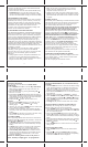
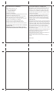
The unit is in a searching mode.
Temperature and readings is
securely registered.
No signals detected.
- - -
GETTING STARTED
WEATHER DISPLAY
After batteries are installed; remote sensor will transmit
temperature data at 45 second intervals. The main unit may
take up to two minutes to receive the initial readings. Upon
successful reception, remote temperature will appear under
the weather forecast section of the main unit’s display (the
default remote channel is channel one). The main unit will
automatically update readings at 45-second intervals.
After communication between the main unit and remote
sensor has been established, secure the remote sensor in
the desired location.
If no signal is received from the remote sensor within two
minutes, dashes [- - -] will be displayed. Press and hold the
DOWN ( ) button on the main unit for two seconds to
initiate another signal search.
PLACEMENT OF THE UNITS
The main unit can be placed on any flat surface indoors.
The remote sensor can be placed indoors or outdoors, on
a flat surface or mounted on the wall.
NOTE: When the temperature falls below freezing, the
batteries in the outdoor remote sensor may have reduced
voltage supply and a shorter effective range. We
recommend using lithium batteries at temperatures of
32°F (0°C) and below.
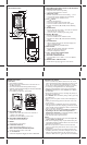
BATTERY INSTALLATION
REMOTE SENSOR
NOTE: Install the batteries; select the channel and
temperature in °C or °F before mounting the remote
sensor.
• Remove the screws from the battery compartment with a
small Phillips screwdriver.
• Set the channel. The switch is located in the battery
compartment. Channel 1 is typically selected if only one
remote sensor is being used.
• Install 2 “AAA” size alkaline batteries (not included)
matching the polarities shown in the battery compartment.
• Replace the battery compartment door and secure the
screws.
• Secure the remote sensor in the desired location.
MAIN UNIT
• Remove the battery compartment door.
• Install 2 batteries (UM-3 or “AA” size 1.5V) matching
the polarity as shown in the battery compartment.
• Replace the battery compartment door.
LOW BATTERY WARNING
A low-battery indicator [ ] will appear next to the indoor
or remote data reading line of the main unit warning that
the corresponding batteries need replacement.
REMOTE AND INDOOR TEMPERATURE
The remote temperature information line is located right
below the weather forecast line of the main unit’s display.
The wave icon is located above the remote channel number
indicates the reception status from the corresponding
remote sensor.
There are three following types of the reception status may
be displayed:
The indoor temperature with the icon is located below
the remote temperature information line.
NOTE: If the indoor or remote temperature goes above or
below operating range stated in specifications, the main
unit’s display ( weather) will show dashes “- - -” on the
corresponding line.
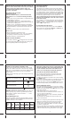
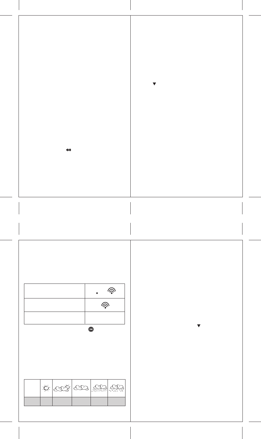
WEATHER FORECAST
This unit is capable of detecting the atmospheric pressure
changes. Based on collected weather data, it forecasts the
weather for the next 12 to 24 hours.
Forecast
is...
Sunny
Partly
Cloudy
Cloudy Rainy
When the
display
shows...
Snowy