


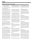

Figure 1: Location of the acoustic axis and
front panel controls
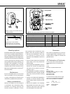
Mounting options
The 8030A offers several mounting options:
The Iso-Pod™ (Isolation Positioner/Decou-
pler™) vibration insulating table stand allows
tilting the loudspeaker for correct alignment of
the acoustic axis. The stand can be attached
to three mounting points allowing vertical
and symmetrical horizontal positioning. On
the base of the loudspeaker is a 3/8” UNC
threaded hole compatible witha a standard
microphone stand. On the rear there are two
M6x10 mm threaded holes for Omnimount
®
size 20.5 brackets.
Maintenance
No user serviceable parts are to be found
within the amplifier unit. Any maintenance
or repair of the 8030A unit should only be
undertaken by qualified service personnel.
Safety considerations
Although the 8030A has been designed
in accordance with international safety
standards, the following warnings and
cautions should be observed to ensure
safe operation and to maintain the loud-
speaker under safe operating conditions:
• Servicing and adjustment must only
be performed by qualified service
personnel. The loudspeaker must not be
opened.
• Do not use this product with an unearthed
mains cable as this may compromise
electrical safety.
• Do not expose the loudspeaker to water or
moisture. Do not place any objects filled
with liquid, such as vases on the loud-
speaker or near it.
• This loudspeaker is capable of producing
sound pressure levels in excess of 85 dB,
which may cause permanent hearing
damage.
• Free flow of air behind the loudspeaker is
necessary to maintain sufficient cooling.
Do not obstruct airflow around the loud-
speaker.
• Note that the amplifier is not completely
disconnected from the AC mains service
unless the mains power cord is removed
from the amplifier or the mains outlet.
Guarantee
This product is guaranteed for a period of
one year against faults in materials or work-
manship. Refer to supplier for full sales and
guarantee terms.
EC Declaration of Conformity
This is to certify that the Genelec Monitoring
System 8030A conforms to the following stan-
dards:
Safety:
EN 60065 / IEC 60065:1998 6th Edition
EMC:
EN 55013: (2001)
EN 55020: (1994), A11: (1996), A12: (1999),
A13: (1999), A14: (1999)
EN 61000-3-2 (2000)
EN 61000-3-3 (1995)
The product herewith complies with the require-
ments of The Low Voltage Directive73/23/EEC,
EMC Directive 89/336/EEC and 93/68/EEC
Signed:
Ilpo Martikainen
Position: Managing Director
Date: 20-April-2004
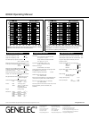
Figure 2: Type of cable needed if
unbalanced source is used (example
shown is RCA output to the XLR input)
Figure 3: Control and connector layout on the rear panel of an 8030A.
Table 1: Suggested tone control settings for differing acoustical environments
Speaker Mounting Position Treble tilt Bass tilt Bass roll-off
Flat anechoic response OFF OFF OFF
Free standing in a damped room OFF OFF OFF
Free standing in a reverberant room OFF -2 dB OFF
Near field or console bridge OFF -4 dB OFF
Near to a wall OFF -6 dB OFF
With a 7050A subwoofer See above See above ON