


Chapter 1 Mechanical Installation
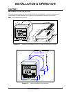
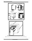
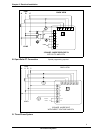
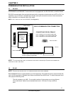
FIRST PUT (16) PIN
CONNECTOR TOGETHER.
(2) 8-32 SCREWS WILL
SIDE VIEW
0.80
(4) 8-32 SCREWS
LINE UP WITH 2 PEMS
ON THE BACK PLATE.
0.198 DIA.
3.375
3.375
4.0 DIA.
1.6875
1.6875
RECOMMENDED
CUTOUT
BACK VIEW
Diagram 1.3
Standard cutout for EPM3000P.
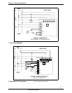
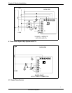
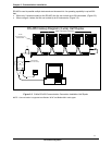
W Port
Diagram 1.4
Optional Communication Converter or DC Output Module Installation
NOTE:
CAREFULLY LINE UP THE GUIDE SCREW AND
8
PIN PORT CONNECTOR TO PREVENT PINS FROM BREAKING
.
2
GE Industrial Systems