


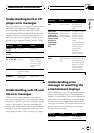
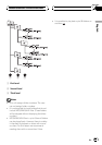


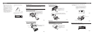
Removing the Unit (Fig. 7) (Fig. 8)
Fig. 7
Fig. 8
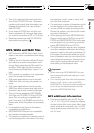
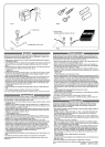
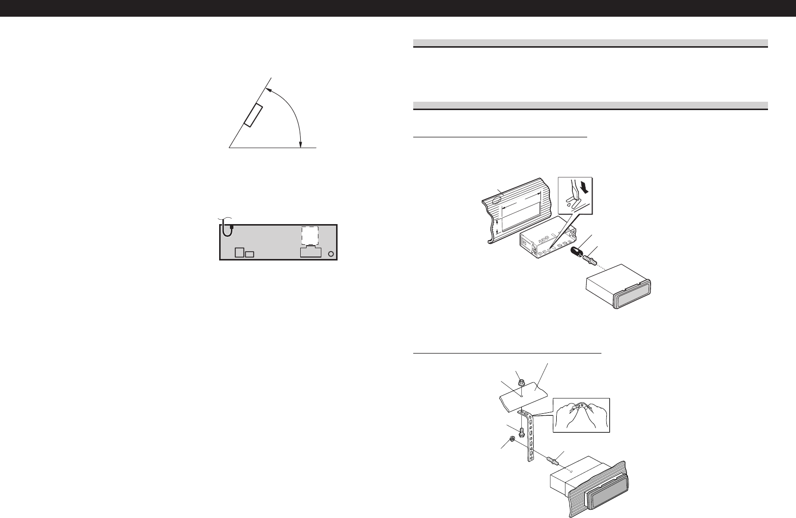
DIN Rear-mount
Installation using the screw holes on the side of the unit
1. Remove the frame. (Fig. 9)
Fig. 9
Insert the release pin into the hole in
the bottom of the frame and pull out
to remove the frame.
(When reattaching the frame, point
the side with a groove downwards
and attach it.)
Frame
Insert the supplied extraction keys into the unit, as
shown in the figure, until they click into place. Keeping
the keys pressed against the sides of the unit, pull the
unit out.
Installation <ENGLISH>
2. Fastening the unit to the factory radio mounting bracket.
(Fig. 10) (Fig. 11)
Select a position where the screw holes of the bracket and
the screw holes of the head unit become aligned (are fitted),
and tighten the screws at 2 places on each side. Use either
binding screws (5 × 8 mm) or flush surface screws
(5 × 9 mm), depending on the shape of the screw holes in
the bracket.
Fig. 10
Fig.11
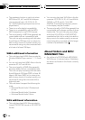
About the fixing screws for the front panel
If you do not operate the removing and attaching the front panel function, use the supplied
fixing screw to fix the front panel to this unit.
Fig. 12
Frame
Insert the release pin into the hole in
the bottom of the frame and pull out
to remove the frame.
(When reattaching the frame, point
the side with a groove downwards
and attach it.)
Screw
Dashboard or Console
Factory radio mounting bracket
Note:
• Before finally installing the unit, connect the
wiring temporarily, making sure it is all connected
up properly, and the unit and the system work
properly.
• Use only the parts included with the unit to ensure
proper installation. The use of unauthorized parts
can cause malfunctions.
• Consult with your nearest dealer if installation
requires the drilling of holes or other modifications
of the vehicle.
• Install the unit where it does not get in the driver’s
way and cannot injure the passenger if there is a
sudden stop, like an emergency stop.
• The semiconductor laser will be damaged if it
overheats, so don’t install the unit anywhere hot
— for instance, near a heater outlet.
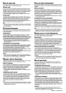
• If installation angle exceeds 60° from horizontal,
the unit might not give its optimum performance.
(Fig. 3)
Fig. 3
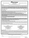
• The cords must not cover up the area shown in the
figure below. This is necessary to allow the ampli-
fires to radiate freely. (Fig. 4)
Fig. 4
60°
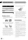
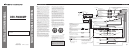
DIN Front/Rear-mount
This unit can be properly installed either from “Front” (conventional DIN Front-mount) or
“Rear” (DIN Rear-mount installation, utilizing threaded screw holes at the sides of unit
chassis). For details, refer to the following illustrated installation methods.
DIN Front-mount
Installation with the rubber bush (Fig. 5)
Fig. 5
Installation without the rubber bush (Fig. 6)
Fig. 6
Nut (5 mm)
Dashboard
Drill a 5.5 – 6.0 mm
diameter hole.
Screw (5 × 16 mm)
Nut (5 mm)
Screw
Strap
Be sure to use the strap to secure the back
of the unit in place. The strap can be bent
by hand to the desired angle.
182
53
Holder
After inserting the holder into the dash-
board, then select the appropriate tabs
according to the thickness of the dash-
board material and bend them.
(Install as firmly possible using the top
and bottom tabs. To secure, bend the
tabs 90 degrees.)
Dashboard
Rubber bush
Screw
Fixing screw