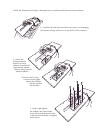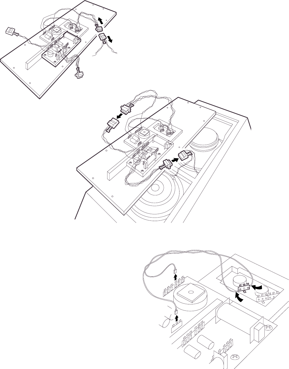
6. Unplug the inline connector between the access
panel and the drivers.
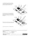
8. Cut the red and black wires soldered to
the 3-pin connector on the input. Unplug
the other ends from the terminal strips on
the existing crossover board. You may dis-
card these wires.
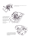
7. Connect the male connector
from the access panel to the
female connector from the
bi-amp crossover board.
Connect the female connector
from the drivers to the male
connector from the bi-amp
crossover board.
Ensure all connectors
are fully mated.


