


8.6.3 EIA-485
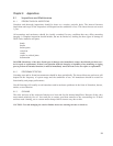
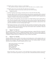
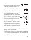
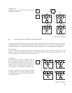
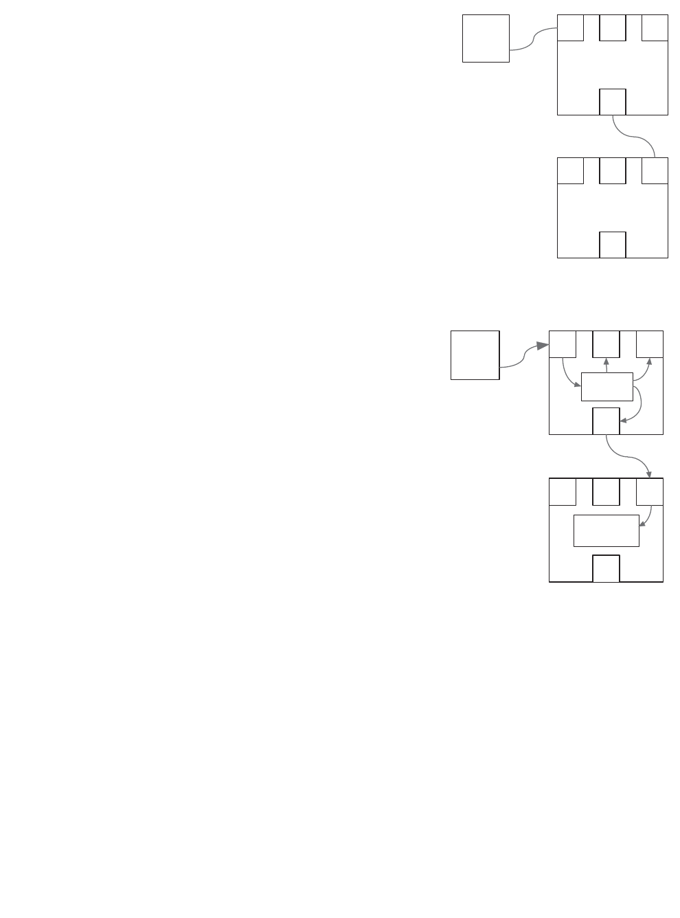
Figure 8.6.3a is the simplest setup with an EIA-485 bus connection to
DSAi module "A" and with a Link Ports connection to DSAi module
"B". These modules could be operating individually or as part of a
cluster.
Only the "A" module EIA-485 port is connected to the PC and there is
a Link Port connection between the "A" PLink and the "B" SLink.
When a DSAi module receives a message (the source is not important)
it checks the message address to see if it matches its own address. If it
matches, the module will use the message.
In the example Figure 8.6.3a, the PC is sending a message to module "A".
The message address matches its own address so it uses the message
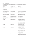
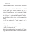
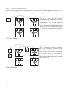
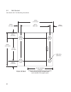
Figure 8.6.3b illustrates what happens when the message is for another
module, in this case module "B". If the message address does not match,
DSAi module “A” will repeat the message out of all its communication
ports except for the one where the message was received. As shown in
Figure 8.6.3b, module "B" would get the message through the Link Ports.
The reason module “A” blindly repeats the message like this is that it
does not know which communication port is connected to module "B"
or to any other modules.
If it received the message through the EIA-485 port, it would repeat the
message to the SLink, the PLink and to the CobraNet CM-1 card, if
installed.
This communication method of blindly passing on control messages is
the basic principle behind the DSAi communication system. It is simple
and works well. However, incorrectly configured control data wiring
will lead to communication loops. Communication loops mean that
communications will fail, often randomly.
8.6.4 EIA-485 CONSIDERATIONS
The EIA-485 connection is very durable when used correctly. It is capable of controlling many devices over
very long distances. It is important to understand the limitations of this networking bus to avoid loss of
communication. Three things are of primary importance.
1. Avoid T-branches: these will invariably cause loops somewhere in the system.
2. Avoid stubs or branches: these will disturb the bus impedance causing signal reflections and resulting
data corruption.
3. Ensure the 120 ohm end of line termination is configured correctly. Incorrect termination means the same
problem and results as in #2.
In the examples below, it does not matter if the modules in the system are configured into clusters or operated
individually. Because of their length restrictions, where Link cables are shown, the modules so connected
would be in close physical proximity.
39
PC
DSA
PILOT
DSA “A”
CM1
SLink
485
PLink
DSA “B”
CM1
SLink
485
PLink
Figure 8.6.3a EIA-485
PC
DSA
PILOT
CM1
SLink
485
PLink
MESSAGE
FOR "B"
DSA "A"
NO MATCH,
RESEND
DSA "B"
ADDRESS MATCHES,
USE IT
CM1
SLink
485
PLink
Figure 8.6.3b EIA-485