


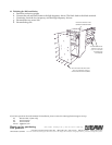
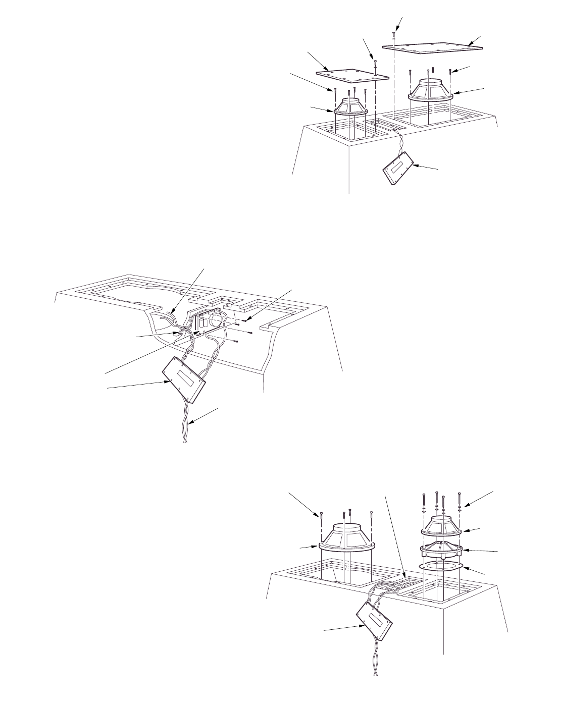
RED AND BLACK LEADS FROM
CROSSOVER THRU PARTITION
& THRU RECTANGULAR CUTOUT
TO HIGH FREQUENCY ASSEMBLY
BLUE AND BLACK LEADS FROM
INPUT THRU PARTITION
TO 15 INCH WOOFER
4X #8 X 1 LG PHILLIPS
HEAD SCREWS
YELLOW AND BLACK
LEADS FROM INPUT
TO 10 INCH MID DRIVER
ELECTRICAL ASS'Y
INCLUDES THE
CROSSOVER BOARD
AND INPUT
(AP6 OR NL8)
4X 1/4-20 X 4-1/2 LG
SOCKET HEAD
CAP SCREWS,
LOCK WASHERS
& M6 FLAT
WASHERS
NEW 10 INCH MID
DRIVER P/N 804097
PHASE PLUG ASS'Y
P/N 0006008
NEW INPUT HARD WIRED
TO INSTALLED CROSS OVER
INPUT OPENING MAY BE USED
TO ACCESS 10 INCH WOOFER
MOUNTING SCREWS
WOODEN APERTURE
RING P/N 0006005
4X 1/4-20 X 1-1/2 LG SOCKET
HEAD CAP SCREWS
BLK P/N 102021
NEW 15 INCH
WOOFER P/N 804016
(CONNECT BLUE
AND BLACK LEADS )
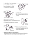
9. Reposition the Enclosure on its face.
With the grille still removed,
a. Reposition the enclosure front down.
b. Remove the 18 hex head screws and flat
washers that attach the two lids.
c. Lift the the two lids from the enclosure.
Retain the hardware and lids.
d. Remove all the polyfill fiber that surounds
the 10” and 15” drivers. Retain the polyfill.
e. Disconnect the 2 electrical leads from both
drivers.
f. Remove the 8 socket head screws that hold
both drivers into the enclosure and lift the
drivers away. Do not retain hardware or
drivers.
g. Remove and discard the 8 input Phillips
head mounting screws and dangle the input to the side of the enclosure as shown.
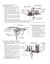
h. Free the electrical leads that pass thru partitions inside the enclosure.
i. Remove and discard the 4 crossover mounting screws and lift the electrical assembly from the enclosure.
4X 1/4-20 X 1 LG SOCKET
HEAD CAP SCREW
S
(DISCARD HARDWARE
)
15 INCH WOOFER
(BLUE AND BLACK
LEADS DISCONNECTED)
REMOVED INPUT
(EIGHT #8 X PHILLIPS HEAD
SCREWS NOT SHOWN-
DISCARD HARDWARE)
4X 1/4-20 X 1 LG
SOCKET HEAD
CAP SCREWS
(DISCARD
HARDWARE)
10 INCH MID DRIVER
(YELLOW AND BLACK
LEADS DISCONNECTED)
SMALL LID
LARGE LID
10X 1/4-20 X 1 HEX HEAD CAP
SCREWS & FLAT WASHERS
(DO NOT DISCARD HARDWARE)
8X 1/4-20 X 1 HEX HEAD CAP
SCREWS & FLAT WASHERS
(DO NOT DISCARD HARDWARE)
10. Installing the new Electrical Assembly
a. Attach the new crossover as shown
with the 4 supplied #8 x 1” long
Phillips head screws.
b. Insert the blue and black leads from
the input board thru the partition
into the 15” woofer chamber.
c. Insert the red and black leads from
the crossover board, thru the parti-
tion, down thru the rectangular hole
into the HF chamber.
d. Seal the hole in the partition with
user supplied putty or silicone.
11. Installing the new Mid Driver and Woofer
a. Place the wooden aperture and new phase
plug into the mid chamber.
b. Position the new 10” driver onto the phase
plug.
c. Insert the 4 supplied 4-1/2 lg screws, lock
washers and M6 flat washers thru the
driver, phase plug and aperture into the
threaded holes in the baffle and tighten.
d. Install the input with the 8 supplied #10
Phillips head screws.
e. Connect the yellow and black leads from
the input board to the 10” mid driver. The
black lead to the black terminal.
f. Attach the new 15” woofer using 4 supplied
1/4-20 x 1-1/2 long screws.
g. Connect the blue and black leads from
the input board to the 15” woofer. The black
lead to the black terminal.
h. Restaple the polyfill into both chambers.