


DISCONNECT
RED AND BLACK
WIRE ELECTRICAL LEADS
2X PHILLIPS HEAD
SCREWS LOCK
AND FLAT WASHERS
(REMOVE AND
DISCARD)
4X SOCKET HEAD CAP SCREWS
LOCK AND FLAT WASHERS
(REMOVE & DISCARD)
HIGH FREQUENCY
HORN ASSEMBLY
REAR BRACKET
REMOVE NUTS, LOCK
WASHER & FLAT WASHER
USING 10mm WRENCH
REUSED REAR BRACKE
T
NEW H4532
HORN P/N 0005848
NEW HIGH FREQUENC
Y
DRIVER P/N 000872
6
4X NEW 1/4-20
X 1" LG BLACK
SOCKET HEAD
CAP SCREWS,
LOCK AND
FLAT WASHERS
2X NEW HORN BRACKET
P/N 0006004
4X NEW 6mm HEX HEAD
SCREWS, LOCKWASHER & FLAT
WASHER (USING 10mm WRENCH
)
HIGH FREQUENCY
HORN ASSEMBLY
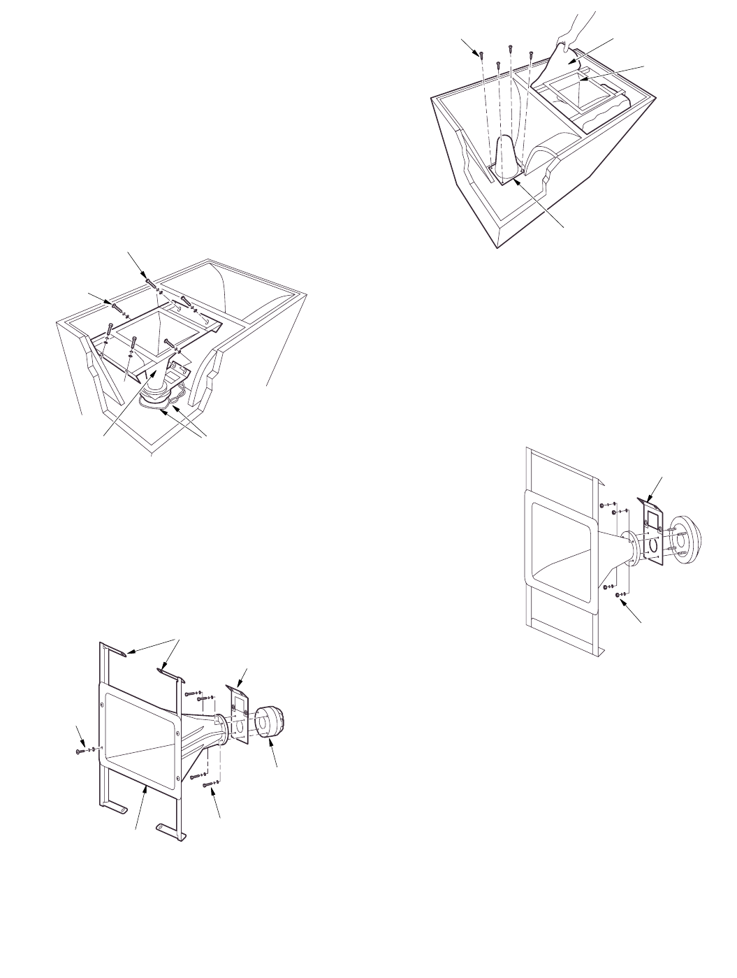
PILLOW (REMOVE AND DISCARD
)
WAVE GUIDE (REMOVE AND DISCARD)
4X PHILLIPS HEAD SCREWS
(REMOVE AND DISCARD)
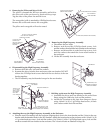
5. Removing the High Frequency Assembly
a. Disconnect the two leads.
b. Remove and discard the 2 Phillips head screws, lock
and flat washers that hold the back bracket to the enclosure.
c. Remove and discard the 4 socket head cap screws, lock
and flat washers that attach the front metal bracket to
the enclosure.
d. Lift the HF assembly from the enclosure.
4. Removing the Pillow and Wave Guide
The pillow is beneath the HF horn assembly and held to
the side walls of the enclosure by hook-and-loop tape.
Tug the sides of the pillow free and lift it out.
The waveguide/grille is attached by 4 Phillips head screws.
Remove the screws and remove the waveguide.
The pillow and waveguide will not be reused.
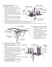
6. Dissassembling the High Frequency Assembly
a. Remove the 4 M6 nuts, lock and flat washers.
b. Separate the driver from the horn and remove the rear bracket. DO NOT
remove the 2 Phillips head screws that hold the two halves of the rear
bracket together.
c. The HF assembly may be discarded except for the rear bracket.
7. Building up the new the High Frequency Assembly
a. Assemble the driver and rear bracket to the round horn
flange using the 4 M6 bolts, lock and flat washers.
b. Attach the 2 brackets to the front horn flange as shown
using 4 black 1/4-20 x 1 lg Phillips head screws, 4 black
lock washers and 4 black flat washers.
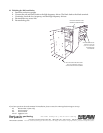
8. Attaching the new the High Frequency Assembly to the Enclosure
a. Place the new HF assembly into the enclosure aligning the 4 slots in the front bracket and the 2 slots in the rear
bracket with the threaded holes in the HF chamber. Attach the front bracket to the enclosure with 4 black 1/4-20
x 1 lg socket head cap screws, lock and flat washers. Use 2 black 1/4-20 x 1 lg Phillips head screws, lock and flat
washers to attach the rear bracket to the enclosure. The 2 elecrical leads are attached in Step 12b.