


3
Operating The Nailer
Read this manual and understand all
safety warnings and instructions before
operating the nailer.
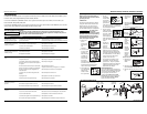
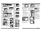
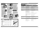
LUBRICATION
This nailer requires lubrication before
using the nailer for the first time and
before each use. If an inline oiler is
used, manual lubrication through the
air inlet is not required on a daily basis.
The work surface
can become
damaged by excessive lubrication. Proper
lubrication is the owner’s responsibil- ity.
Failure to lubricate the nailer properly
will dramatically shorten the life of the
nailer and void your warranty.
1. Disconnect
the air
supply from
the nailer to
add
lubricant.
2. Turn the nailer
so the air inlet
is facing up.
Place 4-5 drops
of 30 W non-
detergent oil
into air inlet.
Do not use
detergent oils, oil additives, or air
tool oils. Air tool oils contain
solvents which will damage the
nailer’s internal components.
3. After adding oil,
run nailer briefly.
Wipe off any
excess oil from
the cap exhaust.
NOTICE
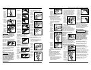
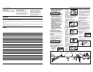
REMOVING NO-MAR DECKING TIP
1. Disconnect air
supply from
nailer.
2. Remove all fasteners from magazine
(See UNLOADING THE
NAILER).
3. Remove no-mar tip retaining ring.
4. Pry no-
mar tip
away
from the
work
contact
element.
5. Replace
retaining
ring onto
no-mar
tip, then
store tip
in safe
place for future use.
INSTALLING NO-MAR DECKING TIP
1. Disconnect air
supply from
nailer.
2. Remove all fasteners from magazine
(See UNLOADING THE NAILER).
3. Remove retaining ring from no-mar
tip.
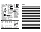
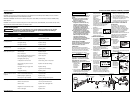
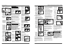
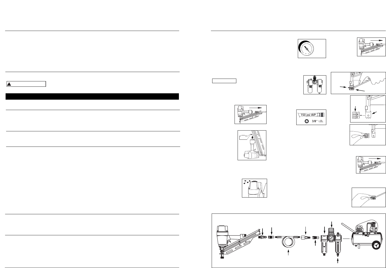
RECOMMENDED HOOKUP
1. The air
compressor
must be able
to maintain a
minimum of 70
psi when the
nailer is being used. An inadequate
air supply can cause a loss of power
and inconsistent driving.
2. An oiler can be
used to provide oil
circulation through
the nailer. A filter
can be used to
remove liquid and
solid impurities which can rust or
“gum up” internal parts of the
nailer.
3. Use 3/8” air
hoses with a
minimum
working
pressure of 150 psi. Use 1/2” air
hoses for 50’ run or longer. For
better performance, install a 3/8”
quick plug (1/4” NPT threads) with
an inside diameter of .315” (8mm)
on the nailer and a 3/8” quick
coupler on the air hose.
4. Use a pressure regulator on the
compressor, with an operating
pressure of 0 - 125 psi. A pressure
regulator is required to control the
operating pressure of the nailer
between 70 and 120 psi.
NO-MAR DECKING TIP
The no-mar decking tip is designed to
eliminate marks caused by the serrated
work contact element (WCE). The no-
mar tip may be removed if not
required (See REMOVING NO-MAR
DECKING TIP). Use tool in single cycle
mode (SEE OPERATIONAL MODES)
when no-mar tip is in place.
70 psi
Min.
OIL
120 psi
Max.
6-Sp
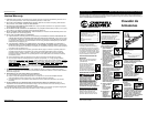
Manual de Instrucciones
Models NS219000, NS289100, NS289500 & NS349000
Retaining
Ring
No-Mar Tip
Work
Contact
Element
No-
Mar
Tip
Sujetadores
La herramienta NS219000 también coloca sujetadores diseñados para: Sears 18465, Porter Cable FR350, Hitachi NR83A, y Senco
FramePro 702XP, 752XP, Ridgid R350RHA y DeWalt D51844, D51845.
La herramienta NS289100 y NS289500 también coloca sujetadores diseñados para: Sears 18420, Atro Helen 90CH, and
Bostitch F28WW, N100S, N865, N805, N16.
La herramienta NS349000 también coloca sujetadores diseñados para: Porter Cable FC 350A, Hitachi NR83AA2, Senco FramePro
701XP, 751XP , Ridgid R350CHA, DeWalt D51822, D51823 y Paslode F-3505.
Recommended Hookup
Quick
Coupler
Air
Hose
Quick Plug
(Optional)
Quick
Coupler
(Optional)
Oiler
Regulator
Filter
Quick
Plug
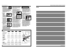
Hay una fuga de aire en el
área de la válvula del gatillo
Hay una fuga de aire entre la
cubierta y la boquilla
Hay una fuga de aire entre la
cubierta y la tapa
La clavadora deja de clavar un
clavo
La clavadora funciona
lentamente o pierde su
potencia
Hay clavos atascados en la
clavadora
Los anillos en O de la cubierta de la válvula del
gatillo están dañados
Los tornillos de la cubierta están flojos
Los anillos en O están dañados
La defensa está dañada
Los tornillos están flojos
El empaque está dañado
La defensa está desgastada
La boquilla está sucia
La suciedad o daños evitan el desplazamiento
libre de los clavos o el mecanismo de impulso en
el cargador
El resorte del mecanismo de impulso está dañado
El flujo de aire hacia la clavadora es inadecuado
El anillo en O del pistón está desgastado o le
falta lubricación
Los anillos en O de la válvula del gatillo están
dañados
Hay fugas de aire
Hay una fuga en el empaque de la tapa
La clavadora no está bien lubricada
El resorte de la tapa del cilindro está roto
El orificio de salida de la tapa está obstruído
La guía del mecanismo de impulso está desgastada
Los clavos no son del tamaño adecuado.
Los clavos están doblados
Los tornillos del cargador o de la boquilla están flojos
El mecanismo de impulso está dañado
Debe reemplazar los anillos en O & chequear el
funcionamiento del elemento de funcionamiento al contacto
Debe apretar los tornillos
Debe reemplazar los anillos en O
Debe reemplazar la defensa
Debe apretar los tornillos
Debe reemplazar el empaque
Debe reemplazar la defensa
Debe limpiar el canal del sistema de impulso
Debe limpiar el cargador
Debe reemplazar el resorte
Chequée las conexiones, la manguera o el compresor
Debe reemplazar los anillos en O. Lubríquelos.
Debe reemplazar los anillos en O
Debe apretar los tornillos y las conexiones
Debe reemplazar el empaque
Necesita lubricar la clavador
Debe reemplazar el resorte
Debe reemplazar las partes internas dañadas
Debe reemplazar la guía
Debe usar los clavos recomendados para esta clavadora
Reemplácelos con clavos en buenas condiciones
Debe apretar los tornillos
Debe reemplazar el mecanismo de impulse de clavos
Guía de Diagnóstico de Averías
Deje de usar la clavadora inmediatamente si alguno de los si guientes problemas ocurre.
repuestos. Podría resultado le heridas graves. Cualquier reparación o reemplazo de piezas los
debe hacer un técnico calificado personal de un centro autorizado de servicio.
!
ADVERTENCIA
Problema Causa Solución
www.chpower.com