


2.3 Wiring and connections.
2.3.1 Mains power.
• Be sure that the mains voltage stated on the unit
complies with the local standard before connecting
the Intellivox to the mains supply.
The maximum power consumption of the Intellivox-2c
model is 450 VA, this figure however is different from
other models (refer to the appropriate datasheet). The
Intellivox is equipped with a 3-pin IEC type mains
inlet / fuse holder. If the fuse needs to be replaced only
replace with the same value. The IEC cable socket
which is supplied with the unit is only suited for use
with stranded wires. The preferred (and most straight
forward) solution is to feed the Intellivox from a mains
power outlet situated nearby the unit using an ‘off the
shelf’ 3 x 0.75 mm
2
(AWG 18) IEC mains cable. If the
mains outlet is located directly behind the Intellivox it
should be recessed to be able to mount the unit flat to
the wall.
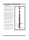
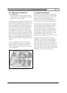
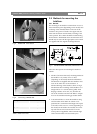
In case it is necessary to make a connection from
massive to stranded wires, the use of an appropriate
clamp is advised. A cross-sectional view of such a
clamp construction is shown in Fig 2. Refer to chapter
3.1 for ordering info.
Fig 2 WAGO massive to stranded wire clamp.
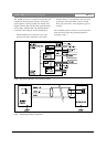
2.4 Signal connections.
All signal connections are realized by using WAGO
series 231 cage clamp connectors. A major advantage
of these connectors is the fact that the connector can
be fitted without the need for soldering. The
connectors can be used with 0.08 mm
2
(AWG 28) to
2.5 mm
2
(AWG 12) wires, both stranded or massive.
The audio and RS-485 signal cable socket is supplied
with the Intellivox. Also three different sized PVC
inserts are supplied which can be inserted in the
connector if small wire sizes are used (usually for the
audio line input connection). The connector for the
SPL/temperature measurement is supplied with the
corresponding sensor. This sensor has to be ordered
separately. Refer to chapter 3.1 for ordering
information if the installation requires extra connectors.
The preferred cable types and the connector pin
configuration is extensively discussed in chapters 3.2
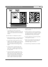
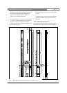
and 3.3. All connectors are located in the Intellivox
connector compartment which is accessible from the
rear and front side of the column (except Intellivox-1b
which is only accessible from the rear). A drawing of
the connector block is shown in Fig 3. A figure similar
to Fig 3 (right side) can be found at the rear side of the
panel that covers the connector compartment.
Intellivox DDC | Installation Manual | Installation Guide
Bosch Security Systems | July 2003
EN
|
8