


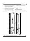

columns can differ substantially from the 2c model.
Mechanical drawings of the other models can be found
in chapter 3.5 or in the respected datasheet.
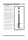
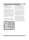
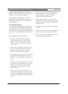
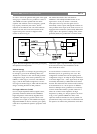
Fig 7 - The LBC 3253/00 dimensions are shown,
including the vertical spacing between the upper and
the lower bracket as well as the vertical offset of the
acoustical reference.
2.5.3 Mounting procedure.
A short general mounting procedure is described, the
actual procedure may differ slightly depending on the
actual circumstances and the chosen mounting method.
It is assumed that the cabling is already prepared and
all connectors are fitted as described in chapter 2.3 and
2.4.
The recommended procedure is as follows:
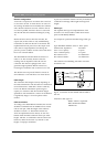
1. Use plugs in combination with hexagon head
screws, this allows the use of a flat key that fits
behind the bracket to fasten the screws. Select a
type with a maximum head size not exceeding
11.5 mm (0.45”).
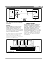
2. Drill the holes for attachment of the brackets into
the wall. It is advised to make use of the slotted
holes (two for each bracket, refer to Fig 6) for
standard vertical mounting of the column.
3. Insert the plugs and screws into the holes. It should
be possible to slide the bracket over the heads.
Check this with a bracket before mounting it to the
column).
4. Check if the chosen mounting holes ensure that the
final position of the column will be in the vertical
angle that is specified (which is usually exactly
perpendicular to the listening area). Use extra
spacers if necessary.
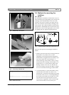
5. Remove the front grill(s) of the Intellivox before
mounting the unit and remove the protection foam.
This can be accomplished by gently lifting the grill
at the positions of the ‘snap-in’ fittings which hold
the grill.
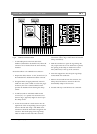
6. Remove the cover of the connector compartment.
Make sure the panel is not interchanged with the
panel of another unit, because this will also
exchange the external serial numbers.
7. Lift the column and slide the brackets over the
heads of the screws. Make sure all cabling is fitted
through the connector compartment and accessible
from the front side.
8. Firmly fasten the screws which secure the brackets
to the wall.
9. Re-check if the column is in an exact perpendicular
position or in the vertical angle that is specified.
10. Insert the connectors and reassemble the connector
compartment cover and the grill(s).
Intellivox DDC | Installation Manual | Installation Guide
Bosch Security Systems | July 2003
EN
|
12