


1
INTRODUCTION
Thank you for purchasing Bowers and Wilkins
Contractor Ceiling Mount (CCM20) speakers.
Since its foundation in 1966, the continuing
philosophy of B&W has been the quest for
perfect sound reproduction. Inspired by the
company’s founder, the late John Bowers, this
quest has entailed not only high investment in
audio technology and innovation but also an
abiding appreciation of music to ensure that the
technology is put to maximum effect.
It is also our policy to make sure the advanced
features pioneered on one product are
incorporated into others we manufacture.
However, no matter how good the speakers
themselves, they must work well into the listening
room and time spent on planning the installation
will reap the reward of many hours listening
pleasure. Please read through this manual fully.
It will help you optimise the performance of
the system.
B&W distribute to over 60 countries worldwide
and maintain a network of dedicated distributors
who will be able to help should you have any
problems your dealer cannot resolve.
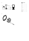
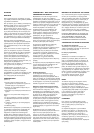
UNPACKING
(figure 1)
• Fold the top carton flaps right back and invert
the carton and contents.
• Lift the carton clear of the contents.
• Remove the inner packing from the product.
Check the contents:
• 2x Baffle with drive units, crossover
• 2x Loudspeaker grille
• 1x Alignment template
• 2x Paint mask
We suggest you retain the packaging for future
use. Remove the grilles from the wall frames and,
to avoid damage, keep them in their plastic
bags (and preferably in the carton) away from
the work area until you are ready to fit them.
POSITIONING – NEW
CONSTRUCTION VERSUS RETROFIT
Check that there is no conflict with other
installations (pipe work, air conditioning, power-
cabling etc.). In existing construction, use a
stud-finding tool to map the construction
accurately and a pipe detector to scan the
proposed installation position. Avoid installing
the speakers in the same cavity as flimsy ducting,
which may be induced to rattle. The speakers
are designed to operate satisfactorily in a wide
range of cavity volumes, ideally above 15 litres
(0.5 cu ft).
The speakers are balanced for half-space
mounting (i.e. flush in a ceiling or soffit).
Placement near a wall/ceiling junction or in a
corner is to be avoided as it may give rise to too
much bass and a boomy quality to the sound.
If possible, keep the speakers more than 0.5m
(20in) from the ceiling edges.
The following sections give guidance on optimum
positioning, but this may be modified in line with
domestic constraints.
Normal Ceiling Applications
For distributed sound, mount the loudspeakers in
the ceiling. The spacing will depend on the
height of the ceiling and the level of sound
required. More speakers played at a lower level
will give better clarity.
Home Theatre Surround Speaker
Applications
The sound from surround speakers should be as
diffuse as possible. This ensures that the frontal
audio image is not distorted by changes of
listener position or head movements. The
speakers should generally be placed behind and
0.6m (2ft) or more above ear height. Ceiling
mounting often gives good results in this
application. The orientation is less important in
this application than in other cases.
WARNING: The CCM speakers produce a static
magnetic field that extends outside the cabinet
boundary. As such They should not be placed
within 0.5m (20in) of equipment that may be
affected by such a field, e.g. Cathode Ray
Tubes in TVs and Personal Computers.
DAMPING THE CEILING CAVITY
In addition, loosely fill the whole section of the
cavity with wadding. Fibreglass and mineral
wool matting supplied for heat insulation are
suitable, but not closed cell foam or expanded
polystyrene. Check that there is no debris that
may fall into the speaker (especially in ceiling
mount situations).
IMPORTANT: YOU SHOULD CHECK THAT THE
MATERIALS YOU USE MEET THE LOCAL FIRE
AND BUILDING REGULATIONS.
FITTING THE WALL FRAME
Existing Construction
Position the template on the ceiling as required
Mark around the outside of the template and cut
the aperture neatly.
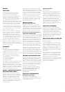
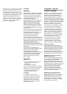
All Methods
(figure 2)
Position the frame in the ceiling and screw in the
4 screws visible from the front of the frame.
These screws swing out clamping dogs that
locate behind the drywall. Ensure that they
have located properly and tighten the screws.
A certain amount of flexing of the frame is
allowed to take up unevenness in the mounting
surface, but do not over tighten the screws as
excessive distortion of the frame may occur.
CUSTOMISING
The frame has a paintable white semi-matte
finish, ready if necessary to be re-finished to
match your own decor. Fit the paint mask before
re-finishing. Do not re-finish the drive units or
baffle area behind the grille. Avoid touching the
drive units, as damage may result.
CONNECTIONS
All connections should be made with the
equipment switched off.
The terminals accept bare wires. Connect the
red (+ve) terminal to the positive terminal of
the amplifier and the black (-ve) to the negative.
Failure to observe correct polarity will result
in ill-defined panning of sounds and strange
phase effects.
When choosing cable, keep the total electrical
impedance (out and back) below the maximum
recommended in the specification. Ask your
dealer for advice, as the optimum cable will
depend on the length required. Cut off excess
length and tie down loose cable to prevent
rattles.