


3
2.7
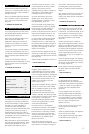
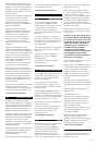
7.1 CHANNEL REAR
These recommendations may also be
used for a 6.1 channel system using two
speakers at the rear, wired in parallel to
the same channel.
Place two speakers behind the listening
area to make an angle of approximately
40º to the centre of the listening area.
(figure 15)
f Continue to section 2.8
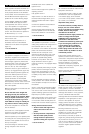
2.8 SURROUND SPEAKER HEIGHT
If you use the system for movies, place
the speakers approximately 60cm (2 ft)
above ear height. (figure 16)
This is also the preferred height for the
dipole mode of the DS8S in all
applications, although it may also be
mounted on the ceiling. Try to keep it
around 0.5m (20 in) from the side wall.
(figure 17)
For all other models, if you are listening
to audio only and there are only one or
two listeners, mount bookshelf speakers
with the tweeters approximately at ear
height.
If there are more listeners, raise the
speakers just above head height to avoid
obstructing the sound to any listener.
(figure 18)
f Continue to section 3.
3 MOUNTING
Model
f Go to
800D/801D/802D 3.1
HTM1D 3.2
803D/803S/804S 3.4
805S/HTM2D/HTM3S/HTM4S 3.5
SCMS 3.6
DS8S 3.7
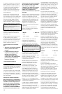
3.1 800D/801D/802D
On delivery, the speakers are fitted with
roller glides to aid movement. Because
of the extreme weight of these speakers,
the rollers can cause indentation of
wooden and other vulnerable floor
surfaces. You should therefore take steps
to protect such surfaces by using an
intermediate layer such as floor tiles or
thick felt. The latter will allow you to glide
the speakers over smooth surfaces if you
push the cabinet low down.
Bass performance may be enhanced by
using the optional adjustable feet. These
are produced separately in a pack of 4
(800 Series Floor Spike Kit, part no.
FP22359). They have 40mm (1.6 in) of
vertical adjustment, allowing a certain
degree of tilt if desired, and are
reversible, having a spike for carpets on
one end and a clear rubber pad for
vulnerable surfaces on the other.
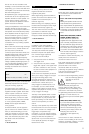
To fit the optional feet, first lay the
speaker down on its side (to avoid
possible damage to terminals or drive
unit diaphragms). (figure 19)
Due to the weight of the speaker, this
should be done by at least two people.
Remove rings and other jewellery to
avoid scratching the surfaces and
provide a soft surface such as a piece of
carpet that the speaker can lie on. You
may also like to wear non-slip gloves.
Do not be afraid to handle the speaker
by lifting on the side of the spherical
midrange 'head'. It is a little unnerving,
because the head is flexibly mounted on
the bass cabinet, but it does come to a
stop and is strong enough to take the
weight of the speaker.
Using the Torx key supplied with the kit,
remove the 4 roller glides from the plinth
of the speaker and replace them with the
feet. (figure 20)
Adjust the feet as described in section 3.3.
f Go to section 3.3.
3.2 HTM1D
Supplied with the speaker are
4 adjustable feet and screws for fitting
them to the cabinet. They have 40mm
(1.6 in) of vertical adjustment, allowing tilt
up to 8º if desired. This is useful, as the
most common situation will be for the
speaker to be mounted on the floor
under a large screen.
The feet are reversible, having a spike for
carpets on one end and a clear rubber
pad for vulnerable surfaces on the other.
Fit the feet during the unpacking
procedure when the underside of the
cabinet is exposed. This allows the inner
packing pieces to remain in place against
the underside of the cabinet as
protection whilst the speaker is rolled
over into the upright position, and be
easily removed afterwards.
First read section 3.3 to familiarise
yourself with the design. If the speaker is
to be tilted back, fit the fr
ont thr
eaded
bosses with the cones facing outwar
ds
(figur
e 21) and the r
ear ones with the
cones facing inwards (figure 22). This is
as illustrated on the separate sheet
placed in the carton.
Scr
ew in the feet with locking ring
attached, with either the spikes or rubber
tips outermost, according to the type of
floor surface. Leave the tips of the feet
protruding beyond the inner packing
pieces for clearance when the speaker is
upright.
After rolling the cabinet onto its feet and
lifting off the carton, remove the inner
packing and adjust the feet as described
in section 3.3
f Continue to section 3.3.
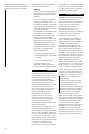
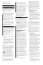
3.3 ADJUSTING THE FEET
The threaded bosses that hold the feet
have a large conical shape on one side
of the flange. For maximum height, fit the
bosses with the conical shape towards
the floor. (figure 21) For minimum height,
have them pointing into the speaker.
(figure 22)
Scr
ew in the feet close to where you
think the final adjustment will be, with the
spikes or the rubber ends outermost as
appropriate to the floor surface. If you do
not intend to tilt the speakers, orient the
bosses with the cones inwards and leave
just enough thread exposed to fit the
locking rings. Fit, but do not tighten the
locking rings.
Stand the speaker upright and adjust the
feet using the metal bar provided to give
the amount of tilt required and to take up
any rocking. (figure 23)
Finally, tighten the locking ring against
the boss, again using the metal bar.
(figure 24)
f Go to section 4.
3.4 803D/803S/804S
For best performance, screw the
adjustable feet into the threaded inserts
in the base of the speaker as appropriate
– spikes for carpets or clear rubber for
wooden and other vulnerable floors.
(figure 25)
Lay the speaker down on its side (to
avoid possible damage to terminals or
drive unit diaphragms). Remove rings
and other jewellery to avoid scratching
the surfaces and provide a soft surface
such as a piece of carpet that the
speaker can lie on.
Screw the lock nuts fully onto the feet
and the feet fully into the base.
(figure 25)
Stand the speaker upright and adjust the
feet to take up any r
ocking.
Finally, tighten the locking rings against
the threaded inserts. (figure 26)
f Go to section 4.