


Specifications are subject to change without notice
AtlasSound.com
1601 JACK MCKAY BOULEVARD ENNIS, TEXAS 75119 U.S.A. • TELEPHONE: (800) 876-3333 • FAX: (800) 765-3435
©2007 ATLAS SOUND LP Printed in U.S.A. ATS002583 RevA 02/07 PP
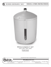
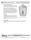
INSTALLATION INSTRUCTIONS
PM SERIES LOUDSPEAKERS 4" AND 8"
5
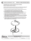
INSTALLATION VIA MOUNTING CABLES (INCLUDED)
General considerations and hardware recommendations
CAUTION: PM series models weigh as much as 21 pounds (7.9kg) – model PM8CX. A fall from almost
any height could result in serious injury or death. Assure that the speaker is firmly mounted to an object
that can handle the weight of the PM speaker. The mounting surface the PM speaker is being attached to
should be able to handle five or more times the weight of the PM speaker
The hardware employed must be safely and securely attached both to the loudspeaker and the structure
in question, using only the mounting holes. A general rule for soft surface installations (wood beams) is to
multiply the corresponding working load limit by 75%: the result will be approximate working load strength.
Use thread locking compound for all installations.
CAUTION:
Mounting the PM loudspeaker may require two people.
When in doubt contact a qualified structural/mechanical engineer for approval of the mounting
materials and methods.
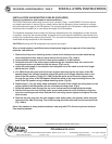
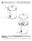
1. Remove the 3 top cover mounting screws, loosen the 2 side top cover screws rotate the top
cover counterclockwise, and pull up to remove the top cover. (Fig 1 and 2)
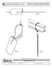
2. Locate suitable support structure in the area the speaker is to be installed.
3. Route the bare end of the main support cable though the included clamp, then around the
mounting structure, and back through the clamp. (Fig 3 and 4)
4. Adjust the cable length in the clamp so that the eyelet end of the cable is at the final height
above the floor. (Fig 5)
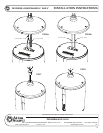
5. (For PM8) Route the eyelet end of the main support cable through the top cover of the PM
speaker, attach the included carabiner clip to the eyelet and the large mounting hole on the
back of the PM speaker. (Fig 6a) (For PM4) Route the eyelet end of the main support cable
through the top cover of the PM speaker, attach the eyelet to the large mounting hole on the
back of the PM speaker using included mounting screw. (Fig 6b)
6. Repeat steps 1-4 for the safety cable and attach it the one of the smaller mounting holes on the
support plate of the PM speaker with the included mounting screw. (Fig 6)
7. Route the speaker cable through the top cover and connect to the appropriate terminals.
8. Position the top cover over the side cover screws and rotate the cover clockwise to align the
top cover mounting screw holes. Reinstall the 3 mounting screws, tighten and tighten the side
cover screws.
9. Slide the top hole plug over the main support cable, safety cable, and speaker cable using the
opening on the side of the plug. Then slide the plug down the cable and into the top cover hole.
(Fig 7 and 8)
Note: If the speaker is being installed outdoors, seal plug with RTV silicone to prevent moisture
from entering speaker.