


©
American Audio
®
- www.AmericanAudio.us - APX-152™/APX-PowerPro™ - Instruction Manual Page 8
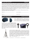
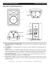
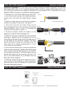
11.
1/4” BALANCED
or
UNBALANCED MICROPHONE INPUT JACK –
This connector is used
as a microphone input connection. This jack will accept either a balanced or unbalanced input.
Be sure to only connect microphones to this jack, line level devices such as CD players and
tape machines should only be connected to the line level input jacks (12 & 13). Follow the text
printed beside the jack on the rear panel for proper input wiring.
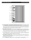
12.
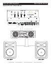
BALANCED XLR LINE INPUT –
This connection is designed to accept a balanced line input
signal from a mixer or other line level device with a balanced output jack. Use a balanced cable
when the signal cable length exceeds 15 feet, this will reduce excessive signal loss. Be sure to
connect only line level input devices such as mixers and tape machines to this jack.
13.
1/4” LINE INPUT JACK –
This jack is used for line level inputs. Connect CD players or Tape
Decks to LINE inputs. Line level musical instruments with stereo outputs such as Rhythm Ma-
chines or Samplers should also be connected to LINE inputs.
14.
XLR PARALLEL OUTPUT JACK –
This jack is used to send the incoming line level signal from
either of the Line Level Inputs Jacks (12 & 13) to another APX-Power Pro™ or other line level
input jack such as a tape recorder.
15.
MICROPHONE INPUT LEVEL –
This knob is used to regulate the output signal of any micro-
FUSE
MIC
LINE
TREBLE
BASS
MASTER
TREBLE
BASS
MASTER
FUSE
11
12
13
14
15
16
17
18
19
20
21
22
23
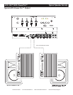
APX-152™/APX-PowerPro™ Controls and Features