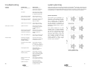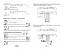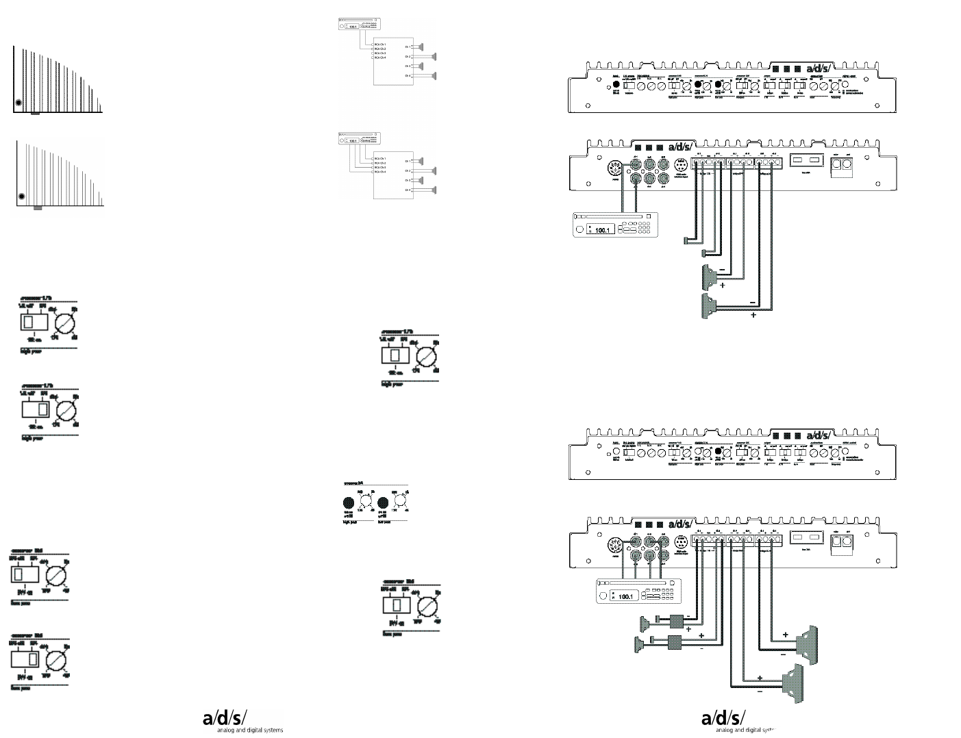
Internal signal routing
2-channel/4-channel input switch – routes RCA input from channels 1/2
to channels 3/4. When the switch is engaged,
channel 1 input is routed to both amplifier
channels 1 and 3 with input channel 2 routed to
amplifier channels 2 and 4.
Switch in the engaged position.
When the switch is disengaged, channels 1, 2, 3,
and 4 receive signal individually from their
respective inputs.
Switch in the disengaged position.
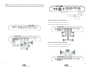
multi-crossTM crossover configuration
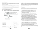
xover control 1/2 The crossover selection for channels 1 & 2 has three possibilities:
When the switch is in the left position, the crossover section of the amplifier is bypassed.
Channels 1 & 2 output is full range.
When the switch is the center position, channels 1 & 2 are filtered through a 12dB per octave
high-pass crossover that is infinitely variable from 45Hz to 5,000Hz.
When the switch is in the right position, channels 1 & 2 receive signal from the crossover
output of channels 3 & 4. Note: When the switch is in the right position, the output level is
controlled by the ch 3/4 level control.
xover control 3/4 The crossover sections dedicated for channels 3 & 4 are activated by depressing the switch next
to each frequency adjustment control. Both high-pass and low-pass crossover’s are infinitely adjustable from 45Hz to
5,000Hz. The high-pass and low-pass sections may be used individually or together to create a bandpass filter.
Note: When using both sections to create a bandpass filter, make sure
you have selected a low-pass frequency which is higher than the high-
pass frequency!
xover control 5/6 The crossover selection for channels 5 & 6 has three possibilities:
When the switch is in the left position, the crossover section of the amplifier is bypassed.
Channels 5 & 6 output is full range.
When the switch is the center position, channels 5 & 6 are filtered through a 12dB per octave
low-pass crossover that is infinitely variable from 45Hz to 5,000Hz.
When the switch is in the right position, channels 5 & 6 receive signal from the crossover output
of channels 3 & 4. Note: When the switch is in the right position, the output level is controlled by
the ch 3/4 level control.
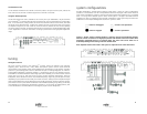
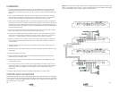
System 4 – PH30 used in 4-channel mode with high-pass tweeters and bandpass midrange. Channels
1and 2 are configured high-pass for the main tweeters and channels 3 and 4, and 5 and 6 are
configured bandpass for main midrange. Channels 4 and 6 are controllled by the 3/4 level control and
crossover section. The amplifier is configured for a 2-channel input.
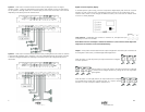
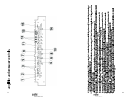
System 5 – PH30 used in 4-channel mode with high-pass main speakers and low-pass subwoofers.
Channels 1 and 2 are configured high-pass for front speakers and channels 3/4, and 5/6 are configured
low-pass for bridged output subwoofers. The amplifer is configured for a 4-channel input. Front/rear
fader adjusts subwoofer level.
815


