


8 AV100
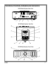
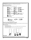
1. POWER ON/OFF Rocker Switch: When pressed to the ON ( I ) position, AC input power is applied to the
radio system, placing it in the standby mode.
2. AC IN Power Connector: 2-prong male power connector for power cable connection to 120V, 60Hz power.
3. SUB OUT Audio Connector: Female RCA audio output connector to external subwoofer speaker.
4. L / R AUX 2 INPUT Connectors: Female RCA audio input connectors for connection to external audio
equipment such as a CD player or other audio output source.
5. S-VIDEO Connector: Provides video output signal from a video iPod* to an external TV or monitor.
6. AM ANTENNA / 300 OHM Terminals: Provide connection for the AM loop antenna for AM signal reception.
7. FM ANTENNA / 75 OHM Connector: Provides connection for the FM antenna F connector for FM signal
reception.
8. Protective Cover: Covers the iPod connector bay when iPod is not in use.
9. VOLUME Control: Continuous rotary control wheel for increasing and decreasing the volume of the audio
output level; clockwise (CW) rotation increases volume, counterclockwise (CCW) rotation decreases
volume.
10. POWER ( ) Pushbutton : Momentarily pressing this button applies power to the radio system, switching
from the standby to on mode and vice-versa.
11. AUX 2 Indicator: This LED indicator lights blue when the AUX 2 mode is selected using the MODE
switch.
12. AUX 1 Indicator: This LED indicator lights blue when the AUX 1 mode is selected using the MODE
switch.
13. iPod Indicator: This LED indicator lights blue when the iPod mode is selected using the MODE switch.
14. FM Indicator: This LED indicator lights blue when the FM mode is selected using the MODE switch.
15. Ventilation Port: Provides cooling air for the audio power output vacuum tubes.
16. AM Indicator: This LED indicator lights blue when the AM mode is selected using the MODE switch.
17. MODE Pushbutton: Each time this button is pressed, the radio system operating mode switches in
sequence from AM through AUX 2 and back again.
18. iPod Connector Bay: Provides male multi-pin connection to an installed iPod; connection compatibility is
achieved with the supplied iPod adapter or with the adapter included with the iPod.
19. TUNE Indicator: Intensity of this amber LED is proportional to station tuning accuracy; the brighter the
LED, the more optimum the reception.
20. Tuning Dial: This vernier control provides selective tuning of the AM and FM stations; the upper dial
indicates the FM frequency range from 87.5MHz to 108MHz, while the bottom dial indicates the AM fre-
quency range from 530kHz to 1710kHz.
21. Audio Power Tube Windows: These windows provide a means of observing the left and right channel
power output vacuum tubes.
22. Audio Headphone ( ) Jack: Provides a 3.5mm connection for audio headphones.
23. Infrared (IR) Window: IR receiver for commands from the remote control.
24. AUX 1 Input Jack: Provides a 3.5mm stereo input connection for an MP3 player or similar device.
25. STEREO Indicator: This green LED illuminates when the FM station is broadcasting in stereo mode.
*Refer to iPod compatibility list on page 9.
Functions of Controls, Indicators and Connectors (Cont)