4-Port USB 2.0 Controller
Datasheet
SMSC USB20H04 Page 11 Revision 1.63 (03-30-07)
DATASHEET
Table 4.4 - Biasing and Clock Oscillator Signals
NAME
BUFFER
TYPE
ACTIVE
LEVEL
DESCRIPTION
RBIAS I-R N/A
External 1% bias resistor. Requires a 12KΩ resistor to ground. Used for
setting HS transmit current level and on-chip termination impedance.
XTAL1/CLKIN ICLKx N/A
External crystal. 24MHz crystal or external clock input when a crystal is not
used.
Connect a 5M ohm resistor from this pin to XTAL2 when a crystal is used.
XTAL2 OCLKx N/A
External crystal. 24MHz crystal. Not connected when using an external clock.
CLKIN_EN I High
Clock Input Enable. When high, an external CMOS clock drives XTAL1.
Table 4.5 - Power and Ground Signals
NAME
BUFFER
TYPE
ACTIVE
LEVEL
DESCRIPTION
VDD3.3 N/A N/A
3.3V Digital Supply. Powers digital pads.
VDD1.8 N/A N/A
1.8V Digital Supply. Powers digital core.
VSS N/A N/A
Signal Ground.
VDDA3.3 N/A N/A
3.3V Analog Supply. Powers analog I/O and 3.3V analog circuitry.
VDDA1.8 N/A N/A
1.8V Analog Supply. Powers 1.8V analog circuitry.
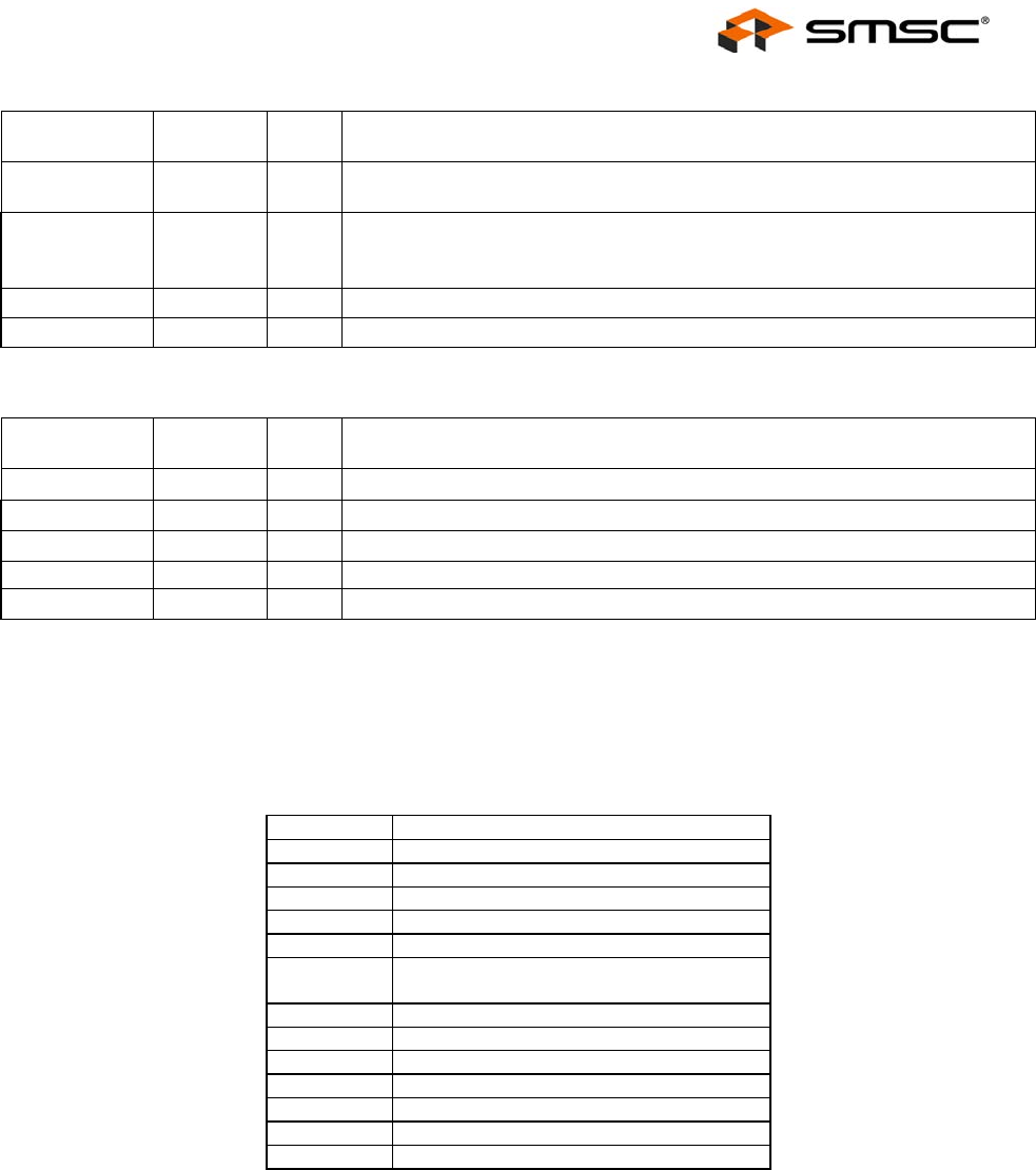
4.2 Buffer Type Descriptions
Table 4.6 – USB20H04 Buffer Type Descriptions
BUFFER DESCRIPTION
I Input
IPU Input with weak internal pull-up resistor.
IPD Input with weak internal pull-down resistor
IS Input with Schmitt trigger
IO8 Input/Output with 8mA drive
IOSD12 Open drain with 12mA sink with Schmitt
trigger. Meets I2C-Bus Spec Version 2.1
O8 Output with 8mA drive
OD8 Open drain with 8mA sink
ICLKx XTAL clock input
OCLKx XTAL clock output
IO-U Defined in USB specification
AO Analog Output
I-R 3.3V Tolerant Analog Pin


