ASSEMBLY / PRE-OPERATION
|lHmlllllnUl ,n,,,,,im,,ll,lll,ll inl nlnll n I n i I ii I I I
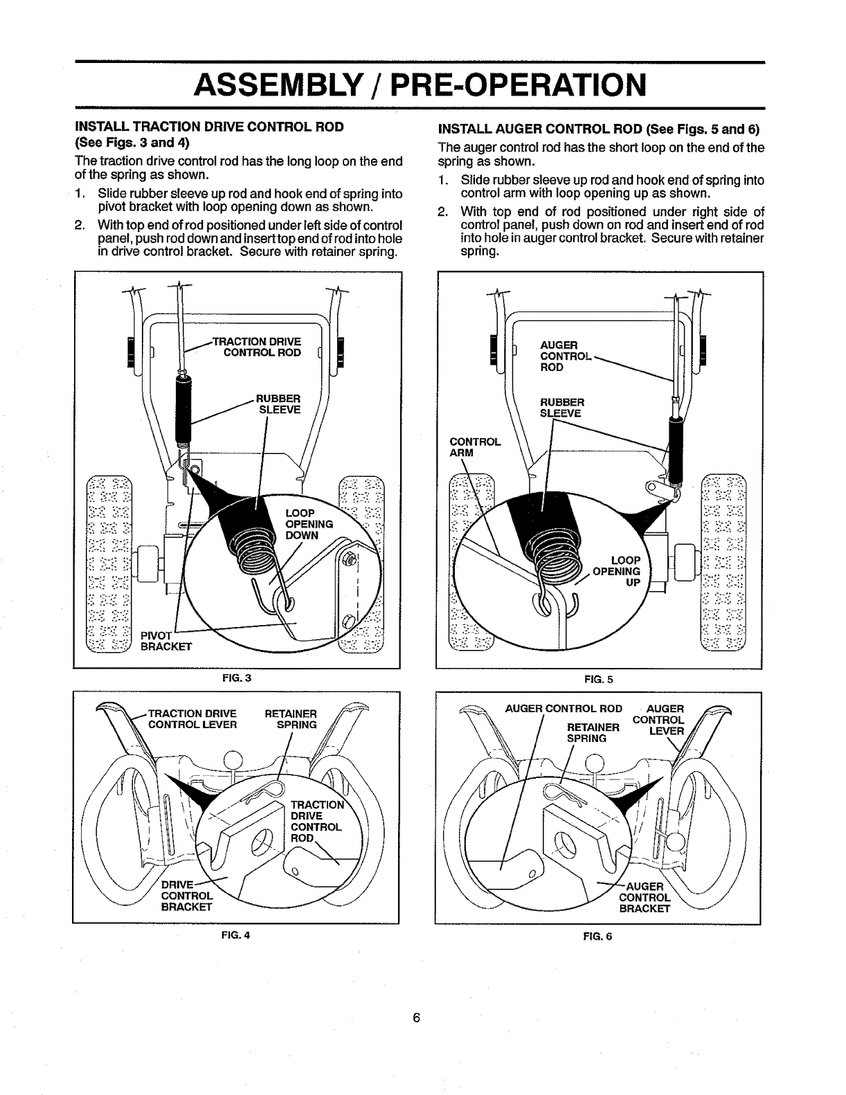
INSTALL TRACTION DRIVE CONTROL ROD
(See Figs. 3 and 4)
The tractiondrive controlrodhas the longlooponthe end
of thespring as shown.
1. Slide rubbersleeve up rodand hookendof springinto
pivot bracketwith loopopeningdown as shown.
2. Withtop end ofrodpositionedunderleftsideofcontrol
panel,push roddownandinserttopendof rodintohole
in drive controlbracket. Secure with retainer spring.
INSTALL AUGER CONTROL ROD (See Figs. 5 and 6)
The auger controlrod hastheshort looponthe endofthe
springas shown.
1. Slide rubbersleeve uprodand hookend of springinto
controlarm withloopopeningup as shown.
2. With top end of rod positioned under right side of
controlpanel, pushdownon rod and insertend of rod
intohole inaugercontrolbracket. Securewithretainer
spring.
DRIVE
CONTROL ROD
BRACKET
FIG. 3
DRIVE RETAINER
SPRING
CONTROL
BRACKET
FIG. 4
CONTROL
ARM
AUGER
FIG. 5
AUGER CONTROLROD AUGER
CONTROL
RETAINER LEVER
SPRING
CONTROL
BRACKET
FIG. 6
=_... = ==...,


