SG1400C3 STUDIO GENERATOR • OPERATION AND PARTS MANUAL — REV. #1 (02/15/12) — PAGE 29
GENERATOR OUTPUTS
GENERATOR OUTPUT VOLTAGES
A wide range of voltages are available to supply voltage for
many different applications. Voltages are selected by using
the voltage selector switch (Figure 10). To obtain some
of the voltages as listed in Table 9 (see below) will require
a fine adjustment using the voltage adjust toggle switch
located on the digital control panel.
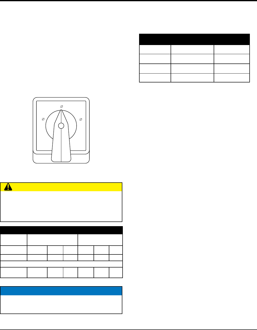
Voltage Selector Switch
The voltage selector switch (Figure 10) is located on the
back side of the Saddle Box Assembly. It has been provided
for ease of voltage selection.
Figure 10. Voltage Selector Switch
.
120/208
277/480 120/240
3
1
3
CAUTION
NEVER change the position of the voltage selector
switch while the engine is running. ALWAYS place
main circuit breaker in the OFF position before selecting
voltage and activate voltage change mode switch.
Table 9. Voltages Available
L1 L2 L3 Output
Terminal Lugs
Voltage Selector Switch
3-Phase 120/208V Position
Voltage Selector Switch
3-Phase 480/277V Position
3Ø
Line-Line
208V 220V 240V 416V 440V 480V
1Ø Line-Neutral 120V 127V 139V 240V 254V 277V
Voltage Selector Switch Single-Phase 240/120V Position
1Ø Line-Neutral/
Line-Line
120V
Line-Neutral
N/A N/A
240V
Line-Line
N/A N/A
NOTICE
Controller has over/under-voltage protection based on
208 V nominal/480 V nominal/240 V nominal voltage.
Generator Amperage
Table 10 shows the maximum amps the generator can
provide. DO NOT exceed the maximum amps as listed.
Table 10. Generator Maximum Amps
Rated Voltage Line Amps Total Amps
1Ø 240 Volt 538 amps 1076 amps
3Ø 208 Volt 466 amps 1400 amps
3Ø 480 Volt 202 amps 606 amps
