05/02 AWB2725-1452GB
Wiring up the I/O signals
11
Wiring up the I/O signals
Wiring up the screw terminal block
Wiring up the spring-loaded terminal block
The spring-loaded terminal block has the same basic design as the
screw terminal block. The difference lies in the way the cable is
connected.
Table 3: Cable connection
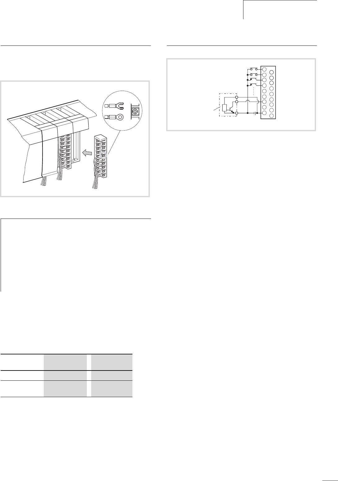
Wiring the digital input module (24 V DC)
• The diodes that are connected in antiparallel to the input
circuits of the module enable operation of the inputs from either
+24 V DC or –24 V DC (see „Internal circuit“ on Page 24).
• When an ON signal is applied to all inputs, the current drawn
via the input contacts is typically 6.9 mA (XIOC-8DI) or 4 mA
(XIOC-16DI).
• Sensors, such as proximity sensors or photoelectric switches,
can be directly attached, provided that they are current-sinking
types (open-collector). Sensors that have a voltage output must
be connected to the inputs via transistors.
• Use cables with a maximum length of 30 metres.
Figure 9: Wiring up the screw terminal block
h
Please observe the following notes:
• All terminals have M3 screws.
• Tighten up the screws to a torque of 0.49 to 0.78 Nm.
• If cable lugs are to be used, then they must have a
maximum outside diameter of 6 mm.
• Do not attach more than 2 cable lugs to one terminal.
• Use a cable with a maximum conductor cross-section
of 0.75 mm
2
, or 0.5 mm
2
if two cable lugs are going to
be fixed to the same terminal.
Conductor Screw
connection
Spring-loaded
connection
solid core 0.5 to 2.5 mm
2
0.34 to 1.0 mm
2
stranded, with
bootlace ferrule
0.5 to 1.5 mm
2
0.14 to 1.0 mm
2
Figure 10: Example of external wiring for the DC input XIOC-8DI/
16DI (here 16 DI)
a Proximity switch
24 V H
a
1
2
3
4
7
C


