PREPARING FOR USE
position and CANNOT be rotated.
b
.The slip nut is threaded completely into the face-
piece and locked securely. It CANNOT be rotated.
c
. The metal locking ring is locked into position and
CANNOT be rotated.
d.There is no loose play in the assembly of parts.
7. Make sure the microphone wire is placed in the relief
groove in the cover assembly and it is not pinched by
t
he cover.
8. Don the facepiece and check the face-to-facepiece
seal. Follow the Facepiece Fit Check procedures in
the MMR Operations and Instructions Manual.
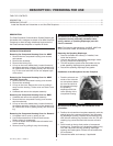
Installing the Component Housing Cover for MMR with
Slide Connection
1. Place the component housing cover over the adapter
assembly.
2. Insert the tab on the cover into the slot in the lens
ring. Press in on the front of the cover until the cover
hook snaps into place.
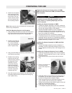
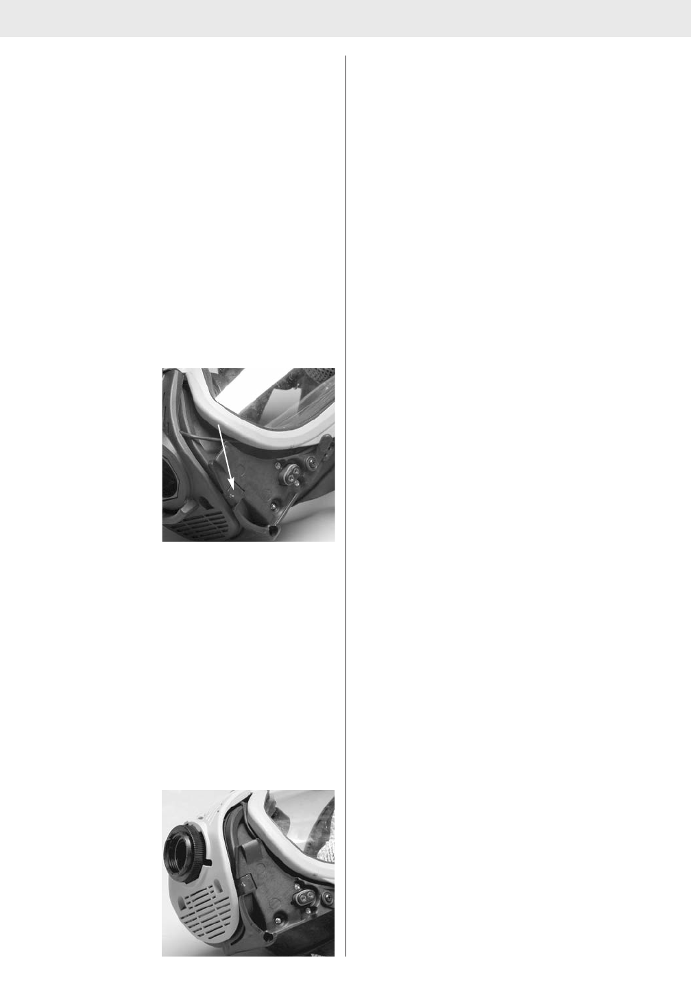
3. Line up the screw holes
in the cover with the
metal tab of mounting
bracket and threaded
inserts in the housing.
4. Place the neckstrap brackets into the cover sockets.
Install the new Phillips screws and tighten.
5. Verify that there is no loose play in the assembly of
parts.
6. Don the facepiece and check the face-to-facepiece
seal. Follow the Facepiece Fit Check procedures in
the MMR with Slide Connection Operation and
Instructions Manual.
Installing the Component Housing Cover Adapter
Assembly for BMR
1. Place the component housing cover over the housing.
2. Insert the tab on the top of the cover into the slot in
the bottom of the lens ring.
3. Press in on the front of the cover until the cover hook
snaps into place.
4. Line up the screw holes
in the cover with the
metal tab of mounting
bracket and threaded
inserts in the housing.
5. Place the neckstrap retaining brackets in the compo-
n
ent housing cover sockets. Install the Phillips screws
and tighten to secure the housing and neckstrap.
6
. Insert the adapter assembly in the facepiece and
hand-tighten.
7. Make sure the microphone wire is placed in the relief
groove in the cover assembly and it is not pinched by
the cover.
8
. Don the facepiece and check the face-to-facepiece
seal. Follow the Facepiece Fit Check procedures in
the BMR Operations and Instructions Manual.
Installing the Component Housing Cover Adapter
Assembly for Demand
1. Place the component housing cover over the housing.
2. Insert the tab on the top of the cover into the slot in
the bottom of the lens ring.
3. Press in on the front of the cover until the cover hook
snaps into place.
4. Ensure that the microphone wire is placed in the
groove in the cover assembly and is not pinched by
the cover.
5. Line up the screw hoes in the cover with the metal tab
of the mounting bracket and threaded inserts in the
housing.
6. Reinstall Phillips screws and tighten to secure hous-
ing.
7. Close bottom half of cover.
8. Perform a qualitative or quantitative respirator fit test
as described in Respirator Fit Test section of the Ultra
Elite APR/CBRN Respirator User Instructions.
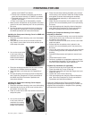
RI Cable Clip Installation (If applicable)
1. Remove the lens ring screw (right side) and discard.
2. Place the cable clip on top of lens ring.
3. Align with screw hole and insert the longer screw pro-
vided with the kit.
4. Tighten the screw into the lens ring.
5. Don the facepiece and check the face-to-facepiece
seal. Follow the Facepiece Fit Check procedures in
Operations and Instructions Manual.
Follow the ClearCommand Communications System
Operating and Maintenance Instructions (P/N 10022714)
supplied with the Amplifier or Amplifier RI for operating
and inspection information.
4
TAL 7001 (L) Rev. 6 - 10022713
Metal Tab