PREPARING FOR USE
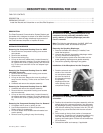
5. Attach the microphone
w
ire connector to the
mounting bracket with
two screws. The con-
nector must be orient-
ed to be inserted into
t
he mounting bracket.
Note: Make sure the wire of microphone is tucked under
the lens ring of facepiece.
Install the Mounting Bracket to the Facepiece
1. Using a Phillips screwdriver, loosen and remove the
screw from left side of the facepiece lens retaining
ring. (Be sure not to lose the nut, if applicable).
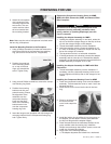
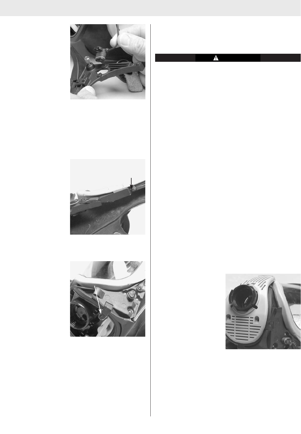
2. Position the metal tab
of the mounting brack-
et, on top of the lens
rings, and reinstall the
screw. Tighten firmly.
3. Using a small Phillips screwdriver, remove the compo-
nent housing ring screw.
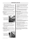
4. Position the mounting
bracket over the com-
ponent housing. Ensure
the alignment of the
metal tab over the
component housing
insert and the align-
ment of the mounting
bracket screw hole
over the component
housing ring hole.
5. Insert the longer screw (supplied with kit) through the
mounting bracket into the component housing ring
hole. Tighten firmly.
Replace the Component Housing Cover for MMR,
M
MR with Slide Connection, BMR, and Demand Ultra
Elite Facepiece.
Be careful not to damage any internal parts of the
component housing assembly (exhalation valve,
s
pring, retainer, or speaking diaphragm) once the
cover is removed.
Installing the Adapter Assembly for MMR
1. Holding the adapter assembly in one hand, rotate the
slip nut so that the octagon flange on the slip nut lines
up with the octagon flange on the adapter.
2. Thread the adapter assembly into the facepiece.
3. Using the spanner wrench, torque the adapter to 12-
27 in.lbs. If necessary, continue to torque until the top
flat on the octagon is horizontal.
4. The bayonets must be in a horizontal orientation.
5. If the bayonets are not horizontal, remove the adapter
assembly and turn the slip nut. Reinstall the adapter
assembly so that the bayonets are horizontal when the
adapter assembly is torqued 12-27 in.lbs.
Installing the Adapter Assembly for MMR with Slide
Connection
1. Thread the adapter assembly into the facepiece. If
necessary, use the component housing cover to con-
tinue to tighten until the top flat on the octagon is hor-
izontal.
Installing the Component Housing Cover for MMR
1. Place the component housing cover over the adapter
assembly. Tilt and rotate the cover to work it over one
bayonet at a time.
2. Insert the tab on the cover into the slot in the lens
ring.
3. Press in on the front of
the cover until the
cover hook snaps into
place.
4. Install the locking ring by sliding it into the groove on
the adapter. (Do not slide it into the space between
the slip nut flange and the adapter flange.)
5. Place the spacers and the neckstrap brackets in the
cover sockets under the locking ring. Install the
Phillips screws through the bracket, spacer, cover and
metal top of bracket and tighten.
6. Verify each of the following features:
a. The adapter bayonets are locked into a horizontal
3
TAL 7001 (L) Rev. 6 - 10022713
Metal Tab
Metal Tab