DESCRIPTION / PREPARING FOR USE
DESCRIPTION
The ClearCommand Communication System Bracket and
Voicemitter Kit is designed to attach to an MSA Ultra Elite
Facepiece to allow the easy attachment and removal of
the ClearCommand Amplifier or Amplifier RI Units.
ULTRA ELITE FACEPIECE
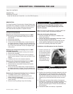
Removing the Component Housing Cover for MMR
1. Remove the two component housing cover screws
and spacers.
2. Remove the neckstrap.
3. Remove the locking ring.
4. Lift up on the cover release hook, located forward of
the adapter assembly opening. Once the release is lift-
ed, remove the cover by pulling it away from the hous-
ing. Tilt the cover and work it over one adapter bayo-
net at a time.
Removing the Component Housing Cover for MMR
with Slide Connection
1. Remove the two component housing cover screws.
2. Remove the neckstrap.
3. Lift up on the cover. Remove the cover by pulling it
away from the housing. Tilt the cover and work it over
adapter.
4. Unthread and remove the adapter assembly.
Removing the Component Housing Cover for BMR
1. Unthread and remove the adapter assembly.
2. Remove the two component housing cover screws
and the neckstrap.
3. Lift up on the cover release hook, located forward of
the adapter assembly opening. Once the release is lift-
ed, remove the cover by pulling it away form the hous-
ing.
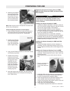
Removing the Component Housing Cover for Demand
1. Lift bottom half of cover by pulling on tab.
2. Use Phillips screwdriver to remove both screws.
Retain screws for reassembly.
3. Lift cover release hood located above threaded con-
nector opening.
4. Remove cover by pulling it away from housing.
Be careful not to damage any internal parts of the
component housing assembly (exhalation valve,
spring, retainer, or speaking diaphragm) once the
cover is removed.
Note: The following procedures are for MMR, MMR with
Slide Connection, BMR, and Demand facepiece.
Removing the Speaking Diaphragm
1. Remove the baffle and nosecup, if installed, from
inside the facepiece.
2. Unscrew and remove the speaking diaphragm retain-
ing ring. Discard the retaining ring.
3. Turn the facepiece upside down and shake out the
metal speaking diaphragm and gasket assembly.
4. Discard the speaking diaphragm and gasket.
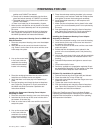
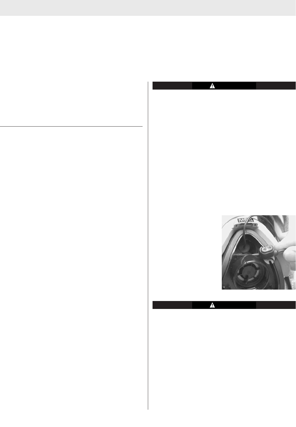
Installation of the Microphone into the Facepiece
1. Feed the wire and con-
nector of the voicemit-
ter microphone assem-
bly from the inside of
the facepiece through
the speaking
diaphragm and inlet
valve opening of the
component housing.
Be careful not to damage the thin membrane in the
voicemitter.
2. Position the voicemitter microphone assembly with the
gasket facing the component housing, into the speak-
ing diaphragm opening. Replace the old retaining ring
with the new retaining ring received in the kit. (The old
retaining ring cannot be used with the new voicemit-
ter.)
3. Push inward on the top front portion of component
housing ring. Thread the new voicemitter retaining ring
onto the component housing speaking diaphragm
opening and hand-tighten. Ensure the voicemitter has
NO movement.
4. Reinstall the baffle and nosecup, if applicable.
2
TAL 7001 (L) Rev. 6 - 10022713
TABLE OF CONTENTS
DESCRIPTION .........................................................................................................................................................................2
PREPARING FOR USE ............................................................................................................................................................2
Install the Bracket and Voicemitter on an Ultra Elite Facepiece..........................................................................................2