MODEL 66-80 VIBRATORY DRIVER/EXTRACTOR
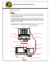
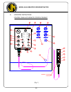
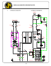
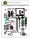
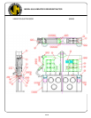
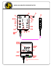
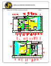
V. HYDRAULIC CIRCUITRY (REFERENCE: HYDRAULIC SCHEMATIC PG V-4)
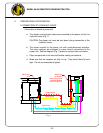
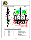
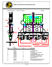
A. HYDRAULIC CLAMP
With the diesel engine running, hydraulic oil is taken from the reservoir by the
clamp pump (P2). The clamp pump flow returns to the reservoir if the clamp
switch on the pendant has not been moved.
Turning the clamp switch on the control pendant to CLOSE activates the CLAMP
CONTROL VALVE (V1). Hydraulic oil is directed to the CLOSE CLAMP side of
the hydraulic CYLINDER (CYL) in the hydraulic clamp. The clamp closes.
Clamping pressure is indicated by the Clamp Pressure Gage (GA-3). When
clamping pressure reaches approximately 5500 PSI (379 Bar), the CLAMP
PRESSURE SWITCH (PS-1) deactivates the CLAMP CONTROL VALVE (V1),
which directs the flow from the clamp pump to the reservoir. Pressure at the
clamp is maintained by the CLAMP CHECK VALVE (CV5). If clamping pressure
falls below 5000 PSI (345 Bar), the CLAMP PRESSURE SWITCH activates the
CLAMP CONTROL VALVE to restore pressure. In the event of hose failure, a
second clamp check valve (CV7), located in the clamp cylinder, will hold the clamp
cylinder closed.
Turning the clamp switch on the control pendant to OPEN activates the CLAMP
CONTROL VALVE (V1). Hydraulic oil is directed to the OPEN CLAMP side of the
hydraulic cylinder. The pressure in the OPEN CLAMP line opens the CLAMP
CHECK VALVES (CV5 & CV7). The clamp opens. Pressure in the OPEN
CLAMP line is indicated by the clamp pressure gage (GA-4).
Pressure in the clamping circuit is limited to 5500 PSI (379 Bar) by the CLAMP
RELIEF VALVE (RV2). The quick-disconnect couplers (QD3 & QD4) permit de-
coupling of the clamp hoses at the power unit.
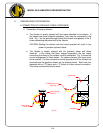
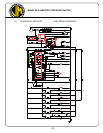
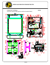
B. VIBRATOR DRIVE
With the diesel engine running, hydraulic oil is taken from the reservoir by the four
DRIVE PUMPS (P1). Oil pressure opens the cartridge C2 and vents the hydraulic
oil back to the reservoir through the RETURN FILTERS (F2), if the vibrator button
(START) has not been pushed.
Pushing the START button, on the control pendant, activates the SOLENOID on
the CONTROL VALVE (V2). By blocking the pilot flow from cartridge C2, the
CONTROL VALVE (V2) causes this cartridge to close, thus directing pump flow to
the VIBRATOR MOTORS (M).
V-1