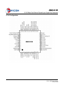
DM9161B
10/100 Mbps Fast Ethernet Physical Layer Single Chip Transceiver
33 Final
Version: DM9161B-12-DS-F01
January 31, 2008
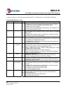
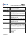
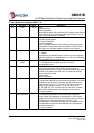
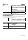
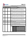
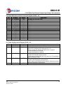
21.11 FDX mask 1, RW Full-duplex Interrupt Mask
When this bit is set, the Duplex status change will not generate the
interrupt
21.10 SPD mask 1, RW Speed Interrupt Mask
When this bit is set, the Speed status change will not generate the
interrupt
21.12 LINK mask 1, RW Link Interrupt Mask
When this bit is set, the link status change will not generate the
interrupt
21.8 INTR mask 1, RW Master Interrupt Mask
When this bit is set, no interrupts will be generated under any
condition
21.7-21.5 Reserved 0, RO Reserved
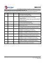
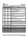
21.4 FDX change 0,RO/LH Duplex Status Change Interrupt
“1” indicates a change of duplex since last register read. A read of
this register will clear this bit
21.3 SPD change 0, RO/LH Speed Status Change Interrupt
“1” indicates a change of speed since last register read. A read of
this register will clear this bit
21.2 LINK change 0, RO/LH Link Status Change Interrupt
“1” indicates a change of link since last register read. A read of this
register will clear this bit
21.1 Reserved 0, RO Reserved
21.0 INTR status 0, RO/LH Interrupt Status
The status of MDINTR#. “1” indicates that the interrupt mask is off
that one or more of the change bits are set. A read of this register
will clear this bit
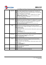
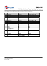
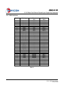
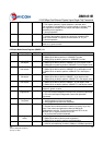
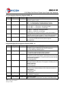
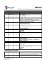
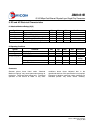
8.14 DAVICOM Specified Receive Error Counter Register (RECR) – 22
Bit Bit Name Default Description
22.15-0 Rcv_ Err_ Cnt 0, RO Receive Error Counter
Receive error counter that increments upon detection of RXER.
Clean by read this register.
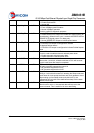
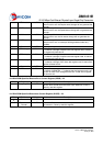
8.15 DAVICOM Specified Disconnect Counter Register (DISCR) – 23
Bit Bit Name Default Description
23.15-23.
8
Reserved 0, RO Reserved
23.7-23.0 Disconnect
Counter
0, RO Disconnect Counter those increments upon detection of
disconnection. Clean by read this register.