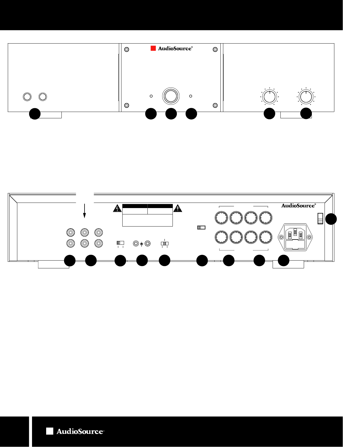
Power
Signal / Clip
Left
Signal / Clip
Right
Left
Right
Balance
Volume
Speakers
A B
AMP102
Stereo Power Amplifier
AMP102 / AMP110
OWNER’S MANUAL
13970 SW 72nd Ave. Portland, OR 97223 • 503.914.4688 • www.audiosource.net
4
1. Power
The front panel power switch switches the AMP102/110 on or off. Red
LEDs behind the faceplate indicate power status. Whenever the amplifier’s
power switch is in the “ON” position the ring around the button is illuminated.
When the amp is “Active” (receiving signal) the side lenses become
illuminated and the signal LEDs show green. During “Standby” status (no
signal) the side lenses are not illuminated and the signal LEDs show orange.
2. Speaker Selector
Selects speaker set ( A or B )
3. Balance
Fades speaker output between the Right and Left Channels
4. Volume
Adjusts amplifier volume.
FRONT PANEL CONTROLS
6. Line 1 Input
A switching input that can be used if a second source is desired and will
take over when a signal is present and has at least a 5mV level. Whenever
there is no signal at this input, or a signal with less than 5mV level, the
amplifier switches back to the Line 2 or “primary” input.
7.
8.
9.
Line 2 Input/Output
The primary line level input and output for a single source connection.
10.
11.
12.
Mode Select Switch
Switches the amplifier from Stereo mode to Bridged mode.
13.
12V Trigger
Allows the AMP102/110 to be powered on by other electronics or to power
on other electronics via a 3.5mm mini phone plug cable.
14.
Power Mode
Sets the power on option of the AMP102/110. Set it to Normal for manual
power on/off. Set to Auto-On for signal sensing. Set to Trigger if the 12V
Trigger input is used.
15.
Right Channel Speaker Output
Right channel terminals for speaker outputs A and B.
Left Channel Speaker Output
Left channel terminals for speaker outputs A and B.
Mains Power Inlet & Fuse Holder
Accepts IEC type line cord. A fuse in the integrated holder provides safety
protection from fault conditions: replace fuse with one of same type
and rating only.
Mains Voltage Selector
Voltage selection switch is preset to 115V (USA). For use in areas which
require 230V contact your dealer. Fuse must be of type and rating marked
on amplifier for use at local mains voltage.
REAR PANEL CONTROLS
4
3
2
1
6
8
9 10
12 13 14
Figure 1. Front Panel
Figu
re 2. Rear Panel
15
7
5 5
5. Clip LEDs
Blinks red during signal clipping. Reduce volume slightly.
Shows solid green (AMP102) or orange (AMP110) during protect mode.
Check speaker wires for shorts or extreme low impedance (< 4 ohms).
11
Light Bar Display Control
Turns light bar display on front panel on or off. Does not control Signal/Clip
LEDs or power button light ring.
Minimum Impedance:
8 ohm Bridged
4 ohm Stereo
AVIS: RISQUE DE CHOC ELECTRIQE
NE
PAS OUVRIR CE CARTER
RESE
RVE AU PERSONNEL AUTORISE
RISK OF FIRE OR ELECTRIC SHOCK
DO NOT OPEN
CAUTION: TO PREVENT ELECTRICAL SHOCK DO NOT REMOVE
COVER. NO USER SE
RVICEABLE PARTS INSIDE. REFER SERVICING TO
QUALIFIED PERSONNEL.
WARNING
: TO PREVENT ELECTRICAL SHOCK DO NOT REMOVE
COVER. NO USER SE
RVICEABLE PARTS INSIDE. REFER SERVICING TO
QUALIFIED PERSONNEL.
CAUTION AVIS
Trigger Normal
Auto On
Mode
Stereo Bridged
115V~ 60Hz 500W
FUSE:T4A
L 250V
FUSE:T2A
L 250V
230V~ 50Hz 500W
MODEL AMP102
Custom Manufactured in China
CAUTION: See User Manual Before
Replacing Fuse
Speaker A
R L
R
L
-
-
-
+ +
+
-
-
+ +
Bridge
Speaker B
-
IN
OUT
12V
Trigger
+
IN
L
R
Line 1
Serial Number:
IN OUT
Line 2 Line 2
On Off
Light Bar Display
Min
Max
Connect
Receiver
Here


