Chapter 10. Dedicated Maps
10-8 ATLAS 550 User Manual 61200305L1-1
incoming DS0 carrying data is mapped to a separate V.35 port and connect-
ed to the router. DS0s carrying voice are collected together (groomed) and
sent to the PBX over a single T1 (T1-D).
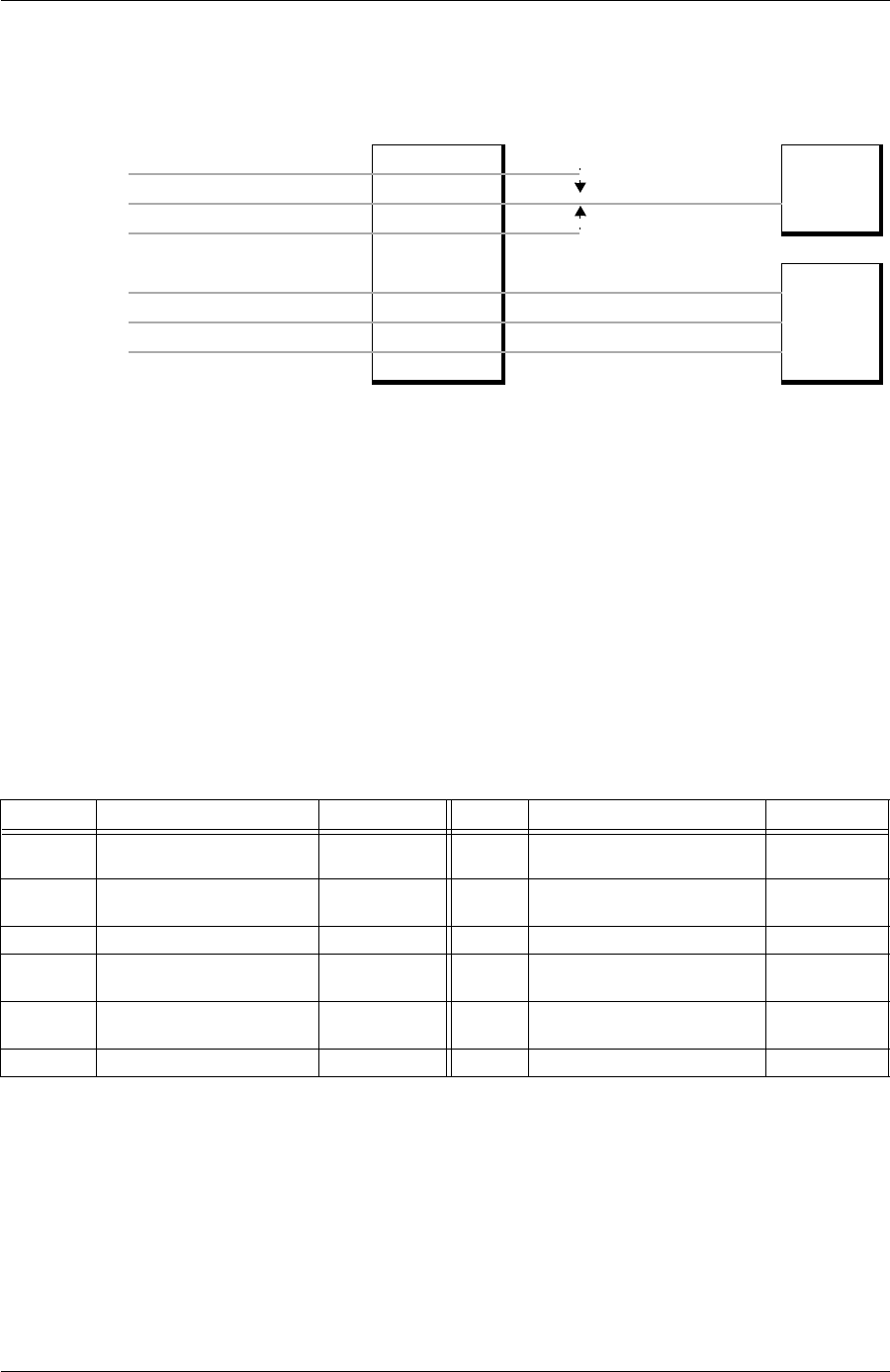
Figure 10-5. Overview of Dedicated Map Example
Designing the Dedicated Map for Example 2
In designing a dedicated map, follow the general procedure listed below:
1. Determine which connections to make and which ports to involve. For
T1 ports, you must also decide which DS0s to use.
2. Configure the ports.
3. Definetheappropriateconnections.
The remainder of this chapter provides the step-by-step procedures for cre-
ating a dedicated map based on example 2 and the connections and ports
listed in Table 10-2 on page 10-8.
T1-A: DS0 1-8, Voice
PBXT1-B: DS0 1-8, Voice T1-D: 1-24 Voice
T1-C: DS0 1-8, Voice
ATLAS 550
T1-A: DS0 9-24, Data V.35 A: Data
External
Router
T1-B: DS0 9-24, Data V.35 B: Data
T1-C: DS0 9-24, Data V.35 C: Data
Table 10-2. Connections And Ports for the Dedicated Map in Example 2
Name ATLAS 550 Port DS0s Name ATLAS 550 Port DS0s
T1-A Voice T1/PRI Network Interface:
Network Slot 1
1-8; RBS On T1-D Dual T1/PRI DSX: Slot 1/Port 2 1-8; RBS On
T1-B Voice T1/PRI Network Interface:
Network Slot 2
1-8; RBS On T1-D Dual T1/PRI DSX: Slot 1/Port 2 9-16; RBS On
T1-C Voice Dual T1/PRI: Slot 1/Port 1 1-8; RBS On T1-D Dual/T1/PRI DSX: Slot 1/Port 2 17-24; RBS On
T1-A Data T1/PRI Network Interface:
Network Slot 1
9-24; RBS Off V.35 A Dual V.35: Slot 2/Port 1 N/A
T1-B Data T1/PRI Network Interface:
Network Slot 2
9-24; RBS Off V.35 B Dual V.35: Slot 2/Port 2 N/A
T1-C Data Dual T1/PRI: Slot 1/Port 1 9-24; RBS Off V.35 C Dual V.35: Slot 3/Port 1 N/A


