


2
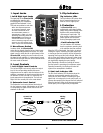
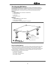
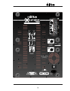
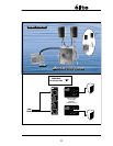
1. Input Jacks
i. Left & Right Input Jacks
The input jacks of the éXcursion1000
are designed for operation with
line-level signals. For convenience,
parallel XLR and balanced ¼-inch
TRS jacks are provided on each side.
Note: The required input level
for full power operation, when
the Level controls are set to
the center detent position, is
approximately +4 dBv (1.2 volts).
Increasing this setting allows the
éXcursion1000 to be driven with
sources that have a low signal
level. Connecting a signal to both
inputs on any one channel (XLR
and ¼-inch) is not recommended.
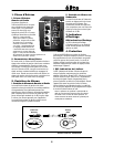
ii. Mono/Stereo Switch
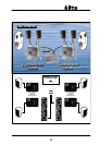
In stereo mode, the éXcursion1000
routes the two signals from the left and right inputs
to the corresponding satellite enclosures. If a mono
signal is sent to either the left or right channel of the
éXcursion1000, enabling the mono mode will route
the signal to both satellites. If a stereo signal is used,
both the left and right channels will be summed when
the mono mode is selected.
2. Level Controls
i. Left & Right Level Controls
The Left and Right Level controls adjust the output
level of the corresponding satellite enclosures.
Adjustments can be made to alter the balance of the
satellites, compensate for signal sources that are not
the standard +4 dBv line level or to tweak the SPL
levels appropriate to the application. The Left and
Right Level are normally set to the center detent.
ii. Subwoofer Level Control
The Subwoofer Level control allows fine-tuning of
the low frequency output. Adjustments can be made
to compensate for signal sources that are not the
standard +4 dBv level.
3. Clip Indicators
Clip Indicator LEDs
The Clip Indicator LED shows when
there is excessive input level on
either the Left or Right Inputs.
4. Protection
The éXcursion1000 uses a
sophisticated, multi-stage limiting
system that prevents clipping of the
amplifiers while accommodating
a wide range of input levels. The
limiter circuitry protects the entire
system against most situations
involving damaging signal levels.
i. Limit Indicator LED
The Limit Indicator LED indicates
when the maximum operating level
for the satellites has been reached.
When the LED is illuminated, the circuitry is actively
limiting the output. Increasing the input signal level
or turning up the Level controls will not increase the
operating level beyond the limit indicated. When the
unit is driven into limiting, the internal Limiter circuit
becomes triggered and will reduce the gain. This will
not significantly degrade the sound quality.
Note: Operating a few dB into limiting will ensure
that the system is operating at its maximum output.
Operating excessively into limiting will make the
system more susceptible to feedback.
ii. Sub Limit Indicator LED
The Sub Limit Indicator LED illuminates when the
maximum recommended operating-level of the
subwoofer has been reached. Increasing the input
signal level or turning up the Level controls will not
increase the operating level beyond the limit indicated.
When the internal Limiter circuit becomes active the
sound quality will not significantly be degraded.
A-Z675 / 1.0PR
CLIP
LEF
T
LIMIT
RIGHT
LIMIT
SUB
LIMIT
RIGHT
LEVEL
12
dB
LEFT
LEVEL
12
dB
SUBWOOFER
LEVEL
12
dB
STEREO
MONO
00
00
00
BAL
BA
L
LEFT
INPUT
RIGH
T
INPUT
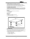
1/4-inch T.R.S.
Phone Plug
Balanced 1/4-inch T.R.S. to Balanced XLR
XLR Plug
(Male)
Tip = 0°
Ring = 180°
Sleeve = Ground
1
Pin 1 = Ground
Pin 2 = 0°
Pin 3 = 180°
2
3