


5
EMER
FAULT
STG1+2
OPERATIONOPERATION
OPERATIONOPERATION
OPERATION
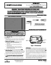
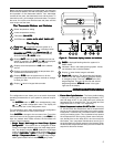
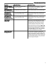
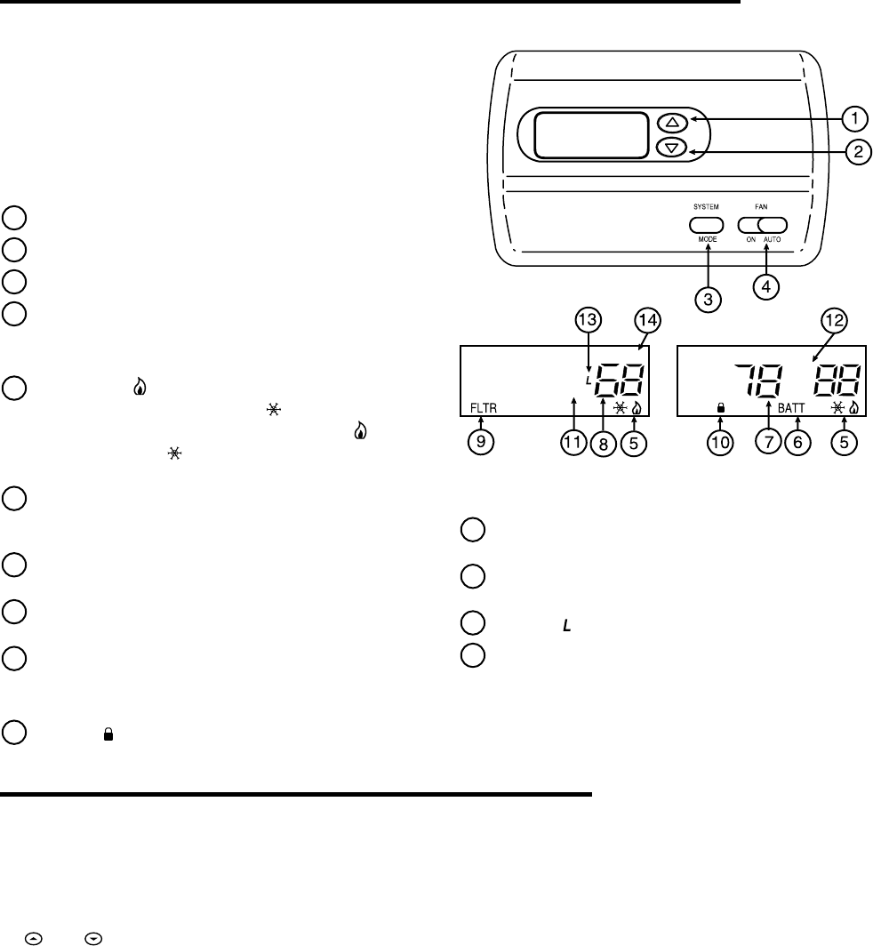
Figure 6 – Thermostat display, buttons and switchesFigure 6 – Thermostat display, buttons and switches
Figure 6 – Thermostat display, buttons and switchesFigure 6 – Thermostat display, buttons and switches
Figure 6 – Thermostat display, buttons and switches
Before you begin programming your thermostat, you should be
familiar with its features and with the display and the location
and operation of the thermostat buttons. Your thermostat
consists of two parts: the thermostat cover and the base. To
remove the cover, pull it straight out from the base. To replace
the cover, line up the cover with the base and press until the
cover snaps onto the base.
The Thermostat Buttons and SwitchesThe Thermostat Buttons and Switches
The Thermostat Buttons and SwitchesThe Thermostat Buttons and Switches
The Thermostat Buttons and Switches
1
Raises temperature setting
2
Lowers temperature setting.
3
FAN switch (
ONON
ONON
ON,
AUTOAUTO
AUTOAUTO
AUTO)
4
SYSTEM button (
COOLCOOL
COOLCOOL
COOL,
AUTOAUTO
AUTOAUTO
AUTO,
HEATHEAT
HEATHEAT
HEAT,
EMEREMER
EMEREMER
EMER,
OFFOFF
OFFOFF
OFF)
The DisplayThe Display
The DisplayThe Display
The Display
5
Flame iconFlame icon
Flame iconFlame icon
Flame icon ( ) is displayed when the system is in
HEAT HEAT
HEAT HEAT
HEAT mode.
Snowflake icon Snowflake icon
Snowflake icon Snowflake icon
Snowflake icon (
) is displayed when
the system is in
COOL COOL
COOL COOL
COOL mode.
Flame iconFlame icon
Flame iconFlame icon
Flame icon ( ) and
Snowflake icon Snowflake icon
Snowflake icon Snowflake icon
Snowflake icon (
) are displayed simultaneously
when thermostat is in
AUTO AUTO
AUTO AUTO
AUTO mode.
6
Displays
BATT BATT
BATT BATT
BATT when the 2 "AA" batteries are low and
should be replaced. Only
BATT BATT
BATT BATT
BATT and
LO LO
LO LO
LO are displayed
when batteries are low with no system power.
7
Displays current temperature or
LO LO
LO LO
LO when batteries
are low.
8
Displays currently programmed set temperature (this
is blank when SYSTEM is OFF).
9
Displays
FLTR FLTR
FLTR FLTR
FLTR when the system has run for the
programmed filter time period as a reminder to change
or clean your filter.
10
Display ( ) when in keypad lockout mode.
11
EMER EMER
EMER EMER
EMER is displayed flashing when the system is in
EMER mode.
12
Indicates a fault in the heating/cooling system. It does
not indicate a fault in the thermostat.
13
Display ( ) when limited range is activated.
14
Stage1 & 2Stage1 & 2
Stage1 & 2Stage1 & 2
Stage1 & 2 indicators: The thermostat shall indicate
when the first and second stage is energized except
in emergency mode. The icon is
STG 1STG 1
STG 1STG 1
STG 1 for the first
stage energized. The icons for the first and second
stage energized are
STG1+2STG1+2
STG1+2STG1+2
STG1+2 located in the upper
right side of the display.
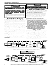
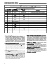
CONFIGURATION MENUCONFIGURATION MENU
CONFIGURATION MENUCONFIGURATION MENU
CONFIGURATION MENU
The configuration menu allows you to set certain thermostat
operating characteristics to your system or personal require-
ments.
Set
SYSTEM SYSTEM
SYSTEM SYSTEM
SYSTEM button to
OFFOFF
OFFOFF
OFF, then simultaneously press
and to enter configuration menu. The display will
show the first item in the configuration menu.
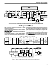
The configuration menu table summarizes the configuration
options. An explanation of each option follows.
Press
SYSTEM SYSTEM
SYSTEM SYSTEM
SYSTEM to change to the next menu item. To exit the
menu and return to the program operation, press
RUNRUN
RUNRUN
RUN. If no
keys are pressed within fifteen minutes, the thermostat will
revert to normal operation.
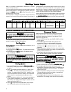
1)
Single Stage, Multi-stage or Heat Pump SystemSingle Stage, Multi-stage or Heat Pump System
Single Stage, Multi-stage or Heat Pump SystemSingle Stage, Multi-stage or Heat Pump System
Single Stage, Multi-stage or Heat Pump System
ConfigurationConfiguration
ConfigurationConfiguration
Configuration – This control can be configured for Heat
Pump or two stage heat/two stage cool multi-stage opera-
tion. The display indicates
MS 2MS 2
MS 2MS 2
MS 2 (default for multi-stage
mode) in the display. The Multi-stage configuration can be
toggled to
SS1SS1
SS1SS1
SS1,
HP2HP2
HP2HP2
HP2, or
HP1HP1
HP1HP1
HP1 by pressing the
Tempera-Tempera-
Tempera-Tempera-
Tempera-
ture Upture Up
ture Upture Up
ture Up or
Temperature DownTemperature Down
Temperature DownTemperature Down
Temperature Down key. In Multi-stage configu-
ration, system button will not have
EMEREMER
EMEREMER
EMERgency mode.
2)
Fast or Slow Cycle SelectionFast or Slow Cycle Selection
Fast or Slow Cycle SelectionFast or Slow Cycle Selection
Fast or Slow Cycle Selection – The factory default setting
is fast cycle, which cycles 1st stage at approximately 1.2°F
and 2nd stage 0.75°F. If you prefer slow cycle, press the
temperature key to change to SL. The 1st stage and 2nd
stage would be 1.5°F and 1.2°F respectively.
3)
Select Compressor Lockout CL OFF or ONSelect Compressor Lockout CL OFF or ON
Select Compressor Lockout CL OFF or ONSelect Compressor Lockout CL OFF or ON
Select Compressor Lockout CL OFF or ON – Selecting
CL ON will cause the thermostat to wait 5 minutes before
turning on the compressor if the heating and cooling system
loses power. It will also wait 5 minutes minimum between
cooling and heating cycles. This is intended to help protect
the compressor from short cycling. Some newer compres-
sors already have a time delay built in and do not require
this feature. Your compressor manufacturer can tell you if
the lockout feature is already present in their system. When
the thermostat compressor time delay occurs it will flash the
setpoint for about five minutes.